

Method and apparatus for removing coolant liquid from moving metal strip
a technology of moving metal strips and coolant liquid, which is applied in the direction of metal-working apparatus, work cooling devices, lighting and heating apparatus, etc., can solve the problems of the intermediate and/or exit temperature of the strip from the mill may exceed acceptable limits, and the inability to meet the requirements of lubricating the surface,
- Summary
- Abstract
- Description
- Claims
- Application Information
AI Technical Summary
Benefits of technology
Problems solved by technology
Method used
Image

Examples
Embodiment Construction
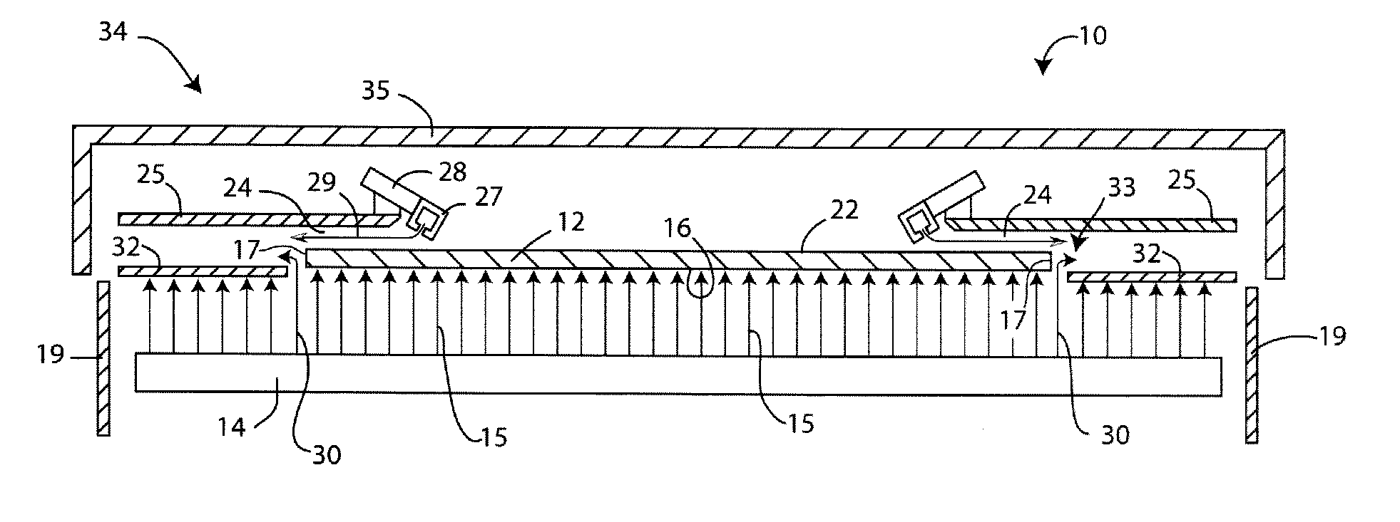
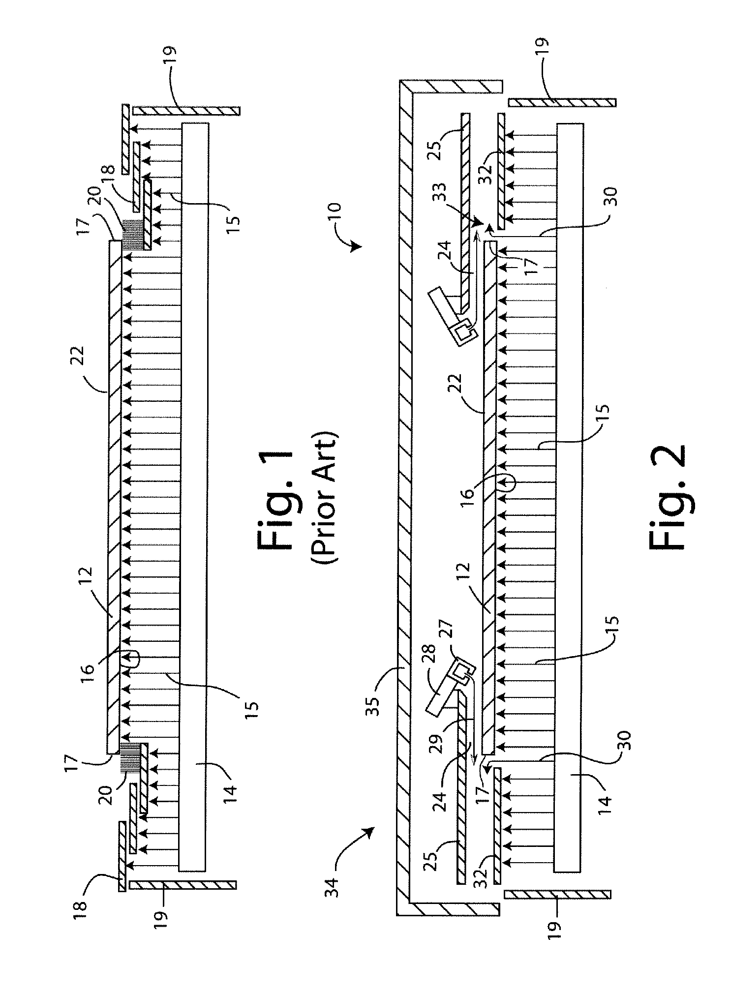
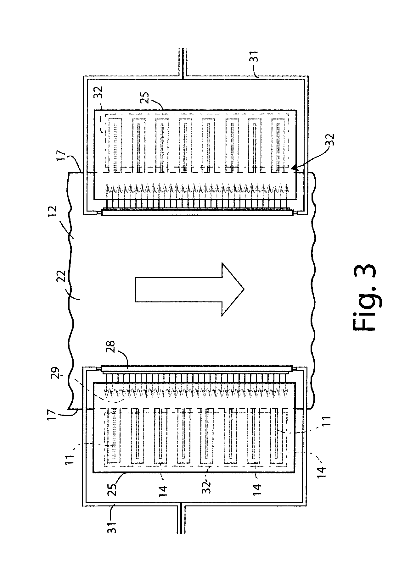
[0010]An exemplary embodiment of the invention provides a method of cooling a metal strip. The method involves continuously advancing a metal strip, having lateral edges, generally horizontally in a direction of strip advance, delivering a coolant liquid onto a lower surface of metal strip from below across the entire width of the strip, preventing the coolant liquid from contacting the upper surface of the metal strip, and optionally subsequently removing said coolant liquid from said lower surface of the strip. The coolant liquid is prevented from contacting the upper surface of the metal strip by forming a gas-directing channel immediately above the upper surface of the metal strip adjacent to at least one of the lateral edges thereof and forcing a gas through the channel in a direction generally away from a center of the strip towards the at least one lateral edge to deflect coolant liquid away from the upper surface of the strip. In this way, coolant liquid emerging from below ...
PUM
| Property | Measurement | Unit |
|---|---|---|
| pressure | aaaaa | aaaaa |
| angle | aaaaa | aaaaa |
| distance | aaaaa | aaaaa |
Abstract
Description
Claims
Application Information