Adaptive bandwidth phase-locked loop

a phase-locked loop and adaptive bandwidth technology, applied in the direction of electrical equipment, automatic control, etc., can solve the problems of consuming a substantial portion of the overall circuit area, affecting the stability of the loop,

Inactive Publication Date: 2012-09-20
NXP USA INC
View PDF5 Cites 12 Cited by
  • Summary
  • Abstract
  • Description
  • Claims
  • Application Information

AI Technical Summary

Problems solved by technology

These parameters introduce undesired variance into the PLL bandwidth and degrade the loop stability of the PLL.
Further, the input capacitance of the loop filter is known to consume a substantial portion of the overall circuit area.

Method used


Image

  • Adaptive bandwidth phase-locked loop
  • Adaptive bandwidth phase-locked loop
  • Adaptive bandwidth phase-locked loop

Examples


Embodiment Construction

[0009]The detailed description of the appended drawings is intended as a description of the currently preferred embodiments of the present invention, and is not intended to represent the only form in which the present invention may be practiced. It is to be understood that the same or equivalent functions may be accomplished by different embodiments that are intended to be encompassed within the spirit and scope of the present invention.

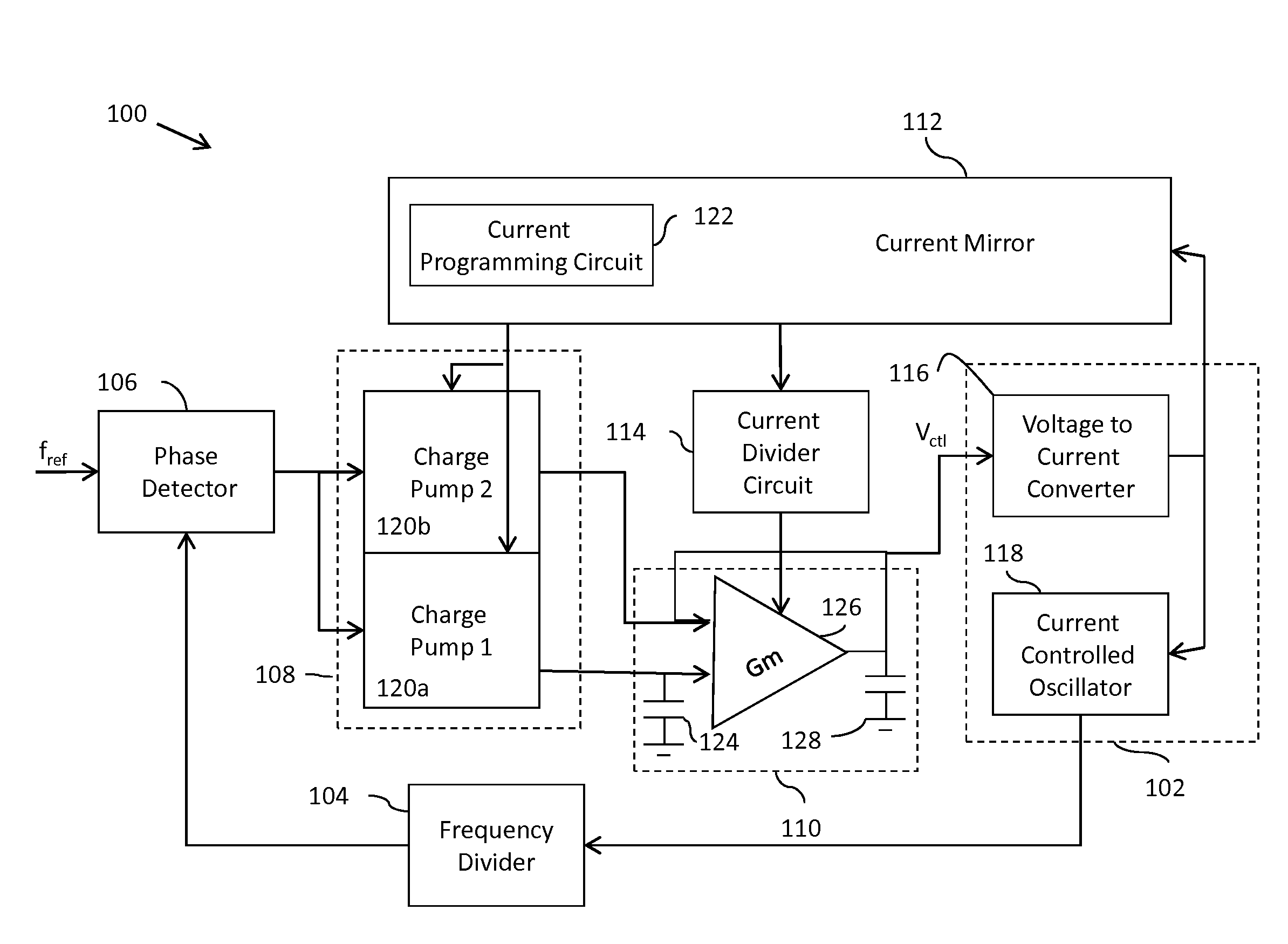
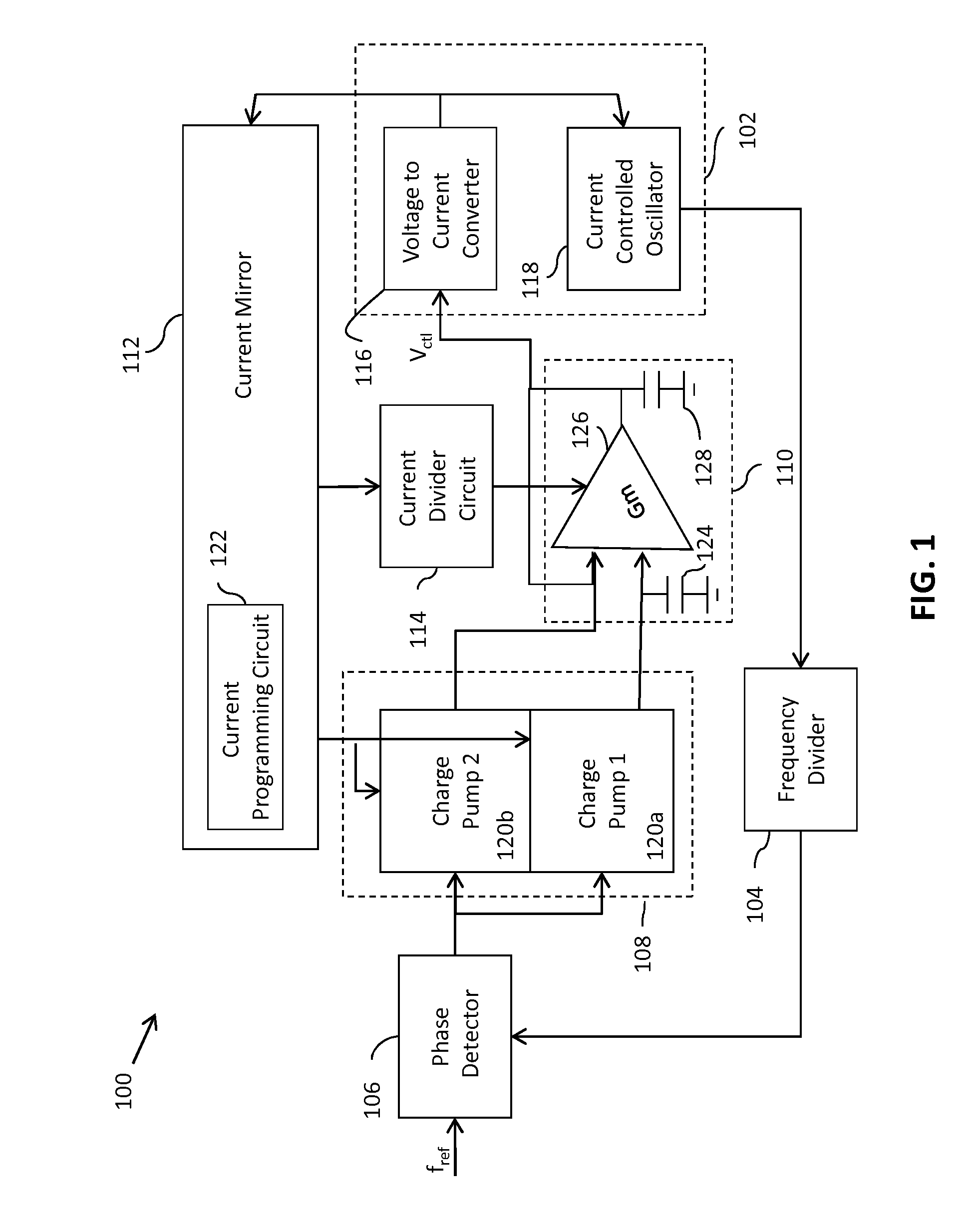
[0010]In an embodiment of the present invention, a phase-locked loop (PLL) is provided. The PLL includes a voltage-controlled oscillator (VCO), which includes a voltage-to-current converter and a current-controlled oscillator (CCO). The voltage-to-current converter converts a control voltage to a first current. The CCO is connected to the voltage-to-current converter and generates an oscillator signal based on the first current. A phase detector is connected to the VCO for generating an error signal based on an input reference signal and a fraction o...


PUM


Abstract

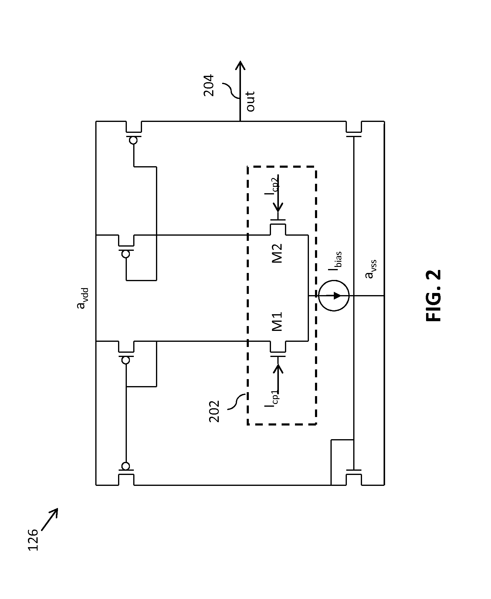
A phase-locked loop (PLL) generates an oscillator signal based on an input reference signal. A voltage-to-current converter converts a control voltage to a first current. A current-controlled oscillator generates the oscillator signal based on the first current. A dual charge pump circuit generates first and second charge pump currents having a predetermined ratio, based on a second current generated by a current mirror circuit and an error (feedback) signal. An active loop filter generates the control voltage based on the first and second charge pump currents. The active loop filter includes an input capacitance that varies with a variation in the predetermined ratio of the charge pump currents. The active loop filter also includes a transconductance stage having a transconductance that varies based on a third current generated by a current mirror circuit. The PLL bandwidth is independent of PVT variations and dependent only on the frequency of the input reference signal. In addition, the size of the input capacitor is relatively small so that the circuit requires very little space.

Description

BACKGROUND OF THE INVENTION[0001]The present invention relates generally to a system for generating an oscillator signal and, more particularly, to a phase-locked loop (PLL) for generating an oscillator signal.[0002]A phase-locked loop (PLL) is a control system that generates an oscillator signal having a constant phase relationship with an input reference signal. PLLs are widely used in various applications such as radios, telecommunications, computers, and other electronic applications. A PLL includes a voltage-controlled oscillator (VCO) for generating the oscillator signal based on a control voltage, and a phase detector for comparing the phase of the oscillator signal with that of the input reference signal and for generating an error signal based on the detected phase difference. The PLL also includes a loop filter for filtering the error signal and generating the control voltage used by the VCO.[0003]For stable operation, the bandwidth of the PLL is required to be dependent o...

Claims


Application Information

Patent Timeline
Patent Type & Authority Applications(United States)
IPC IPC(8): H03L7/08
CPCH03L7/0891
Inventor THAKUR, KRISHNAJAIN, DEEPENDRA K.JAIN, VINOD K.
Owner NXP USA INC
Why Eureka
Try Eureka