Composite electronic component

a technology of electronic components and components, applied in the direction of fixed inductances, structural fixed capacitor combinations, inductances, etc., can solve the problems of insufficient joint strength between the dielectric body and the dielectric body, the property of the magnetic the property of the dielectric body portion may be deteriorated, so as to achieve high joint strength and high joint strength

Active Publication Date: 2012-09-20
NGK INSULATORS LTD
View PDF4 Cites 8 Cited by
  • Summary
  • Abstract
  • Description
  • Claims
  • Application Information

AI Technical Summary

Benefits of technology

[0021]According to this, in the case where the joint layer formed of the material having a higher joint strength to the dielectric body portion and the intermediate layer than a predetermined strength is arranged between the dielectric body portion and the intermediate layer, the joint strength between the joint layer and the dielectric body portion and the intermediate layer is relatively high, even if joint strength between the intermediate layer and the dielectric body portion is low and thus joint strength between the dielectric body portion and the magnetic body portion via the intermediate layer is low; which ensures a relatively high joint strength between the dielectric body portion and the magnetic body portion via the j...

Problems solved by technology

Such diffusion may result in an insufficient joint strength between the dielectric body portion and the magnetic body portion via the intermediate part.
When part of the material of the dielectric body portion or the intermediate part diffuses inside of the magnetic body portion, a property of the magnetic body portion may be deteriorated.
When part of the material of the magnetic body portion or the intermediate part diffuses inside of the dielectric body portion, a property of the dielectric body portion may be deteriorated.
In such a composite electronic component described in Patent Documents 1 and 2 in which there is no countermeasure for suppressing the diffusion of the materials between the dielectric body portion, the magnetic body portion, and the intermediate part, there is a high possibility that the joint strength between the ...

Method used


Image

  • Composite electronic component
  • Composite electronic component
  • Composite electronic component

Examples


first embodiment

1. First Embodiment

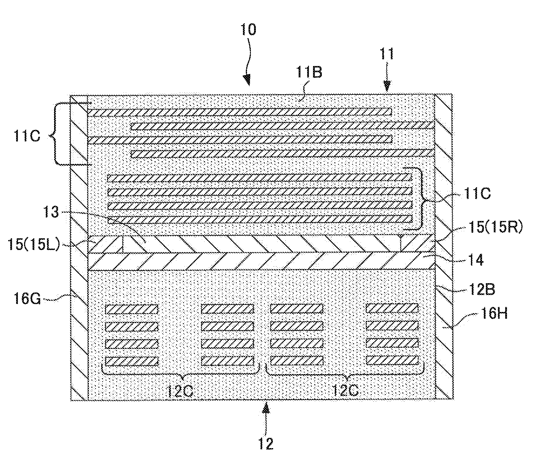
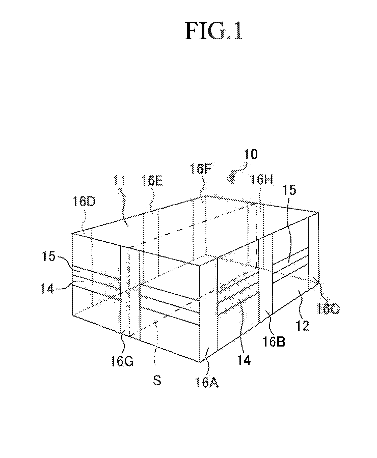
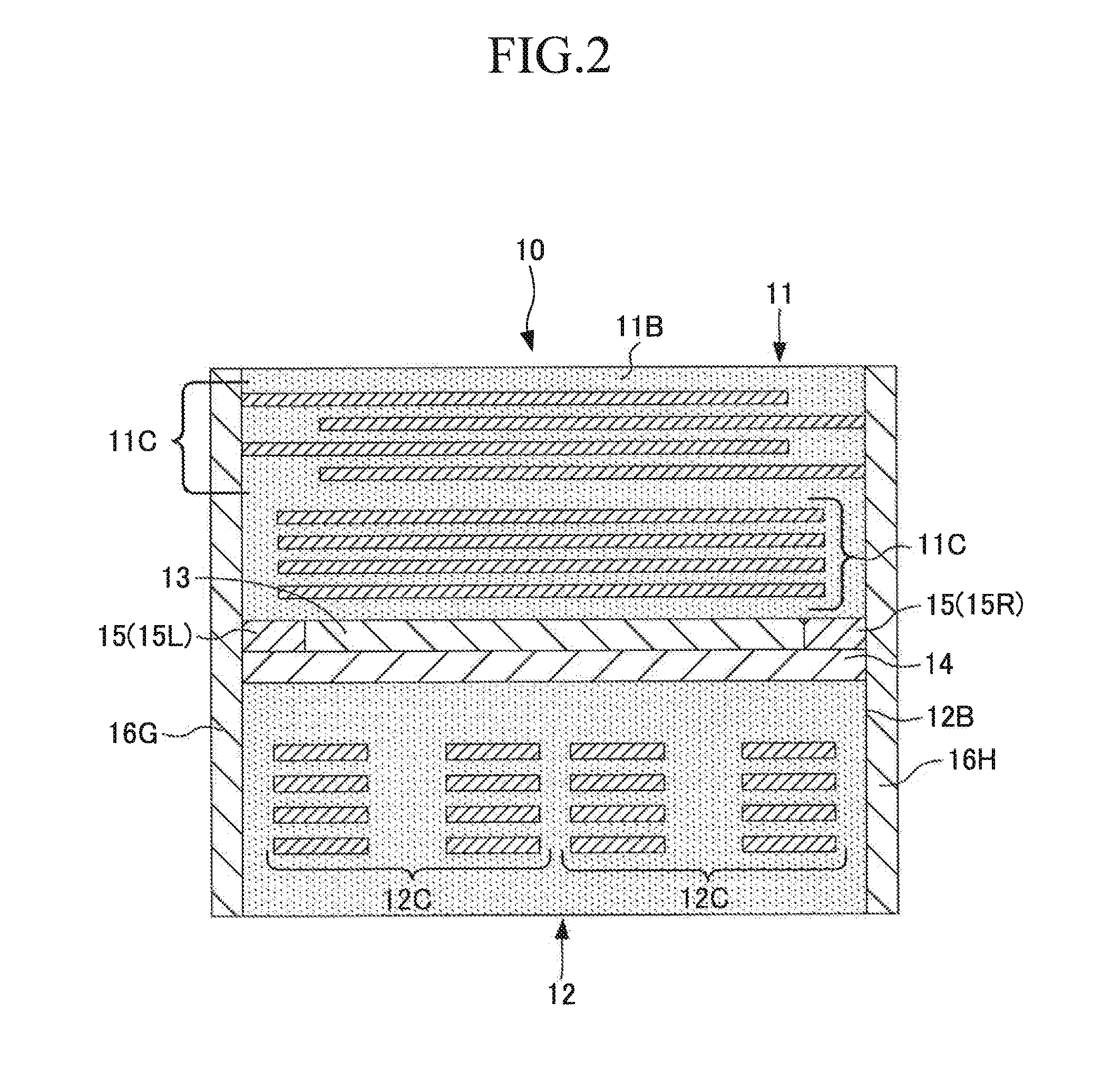
[0032]Hereinafter, embodiments of a composite electronic component of the present invention will be described. One embodiment of the composite electronic component of the present invention (hereinafter, the “first embodiment”) is shown in a perspective view of FIG. 1 and a vertically sectional view of FIG. 2. In FIGS. 1 and 2, the reference numeral 10 denotes a composite electronic component of the first embodiment. As shown in FIG. 1, the composite electronic component 10 has a rectangular parallelepiped shape. As shown in FIGS. 1 and 2, the composite electronic component 10 has a dielectric body portion 11, a magnetic body portion 12, an intermediate layer 13, a first joint layer 14, a second joint layer 15, and external electrodes 16A to 16H as constituent elements thereof. The dielectric body portion 11 and the magnetic body portion 12 have a rectangular parallelepiped shape. The intermediate layer 13 and the first joint layer 14 also have a rectangular parall...

second embodiment

2. Second Embodiment

[0057]Next, a composite electronic component of an embodiment in which the present invention is applied to the case where another joint layer is arranged between the first joint layer 14 and the magnetic body portion 12 in the first embodiment (hereinafter, the “second embodiment”) will be described. The composite electronic component of the second embodiment is shown in a perspective view of FIG. 3 and a vertically sectional view of FIG. 4. In FIGS. 3 and 4, the reference numeral 20 denotes a composite electronic component of the second embodiment. As shown in FIG. 3, the composite electronic component 20 has a rectangular parallelepiped shape. As shown in FIGS. 3 and 4, the composite electronic component 20 has a dielectric body portion 21, a magnetic body portion 22, an intermediate layer 23, a first joint layer 24, a second joint layer 25, a third joint layer 27, and external electrodes 26A to 26H as constituent elements thereof. The dielectric body portion 2...


PUM


Abstract

The present invention relates to a composite electronic component having a dielectric body portion inside of which a conductive body is provided, and a magnetic body portion inside of which a conductive body is provided. In the present invention, a layer made of a metal material is arranged between the dielectric body portion and the magnetic body portion as an intermediate layer.

Description

TECHNICAL FIELD[0001]The present invention relates to a composite electronic component.BACKGROUND ART[0002]Patent Document 1 describes a LC composite component serving as a composite electronic component. The LC composite component is formed by jointing a part made of a dielectric material (hereinafter, this part is called the “dielectric body portion”) and a part made of a magnetic material (hereinafter, this part is called the “magnetic body portion”) via a part made of a specific material (hereinafter, this part is called the “intermediate part”). In the LC composite component, plural pairs of electrodes including conductive bodies are provided inside of the dielectric body portion, the dielectric body portion functions as a capacitor, a coil including a conductive body is formed inside of the magnetic body portion, and the magnetic body portion functions as an inductor.[0003]The dielectric body portion of the composite electronic component described in Patent Document 1 is forme...

Claims


Application Information

Patent Timeline
IPC IPC(8): H01F37/00H01G4/002
CPCH01F17/0013H01G4/40H01G4/30H01F2017/0026
Inventor OHIRA, NAOTOSHIMOGAWA, NATSUMIYAMAGUCHI, HIROFUMINANATAKI, TSUTOMU
Owner NGK INSULATORS LTD
Why Eureka
Try Eureka