Ablation treatment planning and device

a technology of treatment planning and device, applied in the field of ablation treatment planning and ablation treatment planning, can solve the problems of cell death, difficult to precisely control the effect of ablation volume, and inability to accurately and reliably assis

Active Publication Date: 2012-09-20
KONINKLIJKE PHILIPS ELECTRONICS NV
View PDF34 Cites 50 Cited by
  • Summary
  • Abstract
  • Description
  • Claims
  • Application Information

AI Technical Summary

Benefits of technology

[0015]A success of a percutaneous ablation such as a radio frequency ablation, a cryo-ablation or a microwave ablation, may mainly depend on an accuracy concerning a location and an orientation with which an ablation needle is inserted, enabling to destroy an entire tumour while avoiding damages on other organs and minimizing risks of local reoccurrence.
[0016]Recently, a new live 3D needle image planning / guiding procedure has been proposed for example in WO 2007 / 113703 A2. The needle image planning / guiding system proposed therein has been invented by the applicant of the present invention and is also referred to as XperGuide. This system may allow bringing percutaneous needle interventions back to the angio lab. Such navigational tool may create an overlay of live fluoroscopy imaging and 3D soft tissue imaging that may provide information on needle path and target. XperGuide may be used in a wide range of clinical procedures from biopsies and drainages to ablations. Therein, XperGuide imaging may provide for a live 3D feedback on advancement of a needle for extra guidance and control during interventional procedure. This may allow physicians more freedom in planning and performing needle punctures particularly at oblique angles. Furthermore, optimized patient access for every step of such procedure may be offered. Accordingly, needle guidance procedures may be performed in the angio lab where all the necessary materials may be at hand. Life fluoroscopy may be combined with 3D soft tissue imaging supporting the physician in managing the patient.
[0019]Therefore, it is proposed herein to use a more graphics oriented constructive means of tagging an ablation area, thereby allowing to easily plan an ablation volume within a patient's body comprising a region of interest via visualization to a user and, subsequently, allowing to guide an ablation needle to a location and in an orientation such that such ablation volume may be realized.
[0023]A gist of the present invention may be seen as based on the idea to use a more graphics based approach in order to visualize an ablation volume to be planned within a 3D image of a region of interest such that the ablation area may be visualized in any desired viewing plane orientation. In such graphics based approach, specific image processing procedures such as clipping imaging planes, tagging portions of the 3D model data of the ablation volume through the desired MPR plane into a stencil buffer, blending such tagged portions to a colour buffer, culling an outside or an inside of the ablation volume model, merging of ablation volumes, model transformation for scaling, positioning and / or transforming the 3D model data of the ablation volume in a predetermined direction, etc. may be advantageously used in order to visualize the ablation volume within the region of interest such that a physician may easily plan a subsequent surgical intervention and then guide the ablation needle(s) according to such plan.
[0024]In other words, a physician having a 3-dimensional image of a region of interest, e.g. previously acquired with X-ray imaging, may plan an ablation intervention by experimentally inserting simulated ablation volumes having a predictable shape and size into the visualized region of interest within a physiological 3D image at a selectable location and a selectable orientation. The ablation volume should be visualized within the physiological 3D image in a way such that the physician may easily determine whether all tumourous tissue is enclosed within the planned ablation volume. Therein, instead of analytically calculating intersecting areas of a viewing plane with an ellipsoid ablation volume, which may be a difficult task if arbitrarily oriented viewing planes and ablation volume orientations are to be visualized, a graphical approach is used in which the planned ablation volume is visualized within the physiological 3D image using graphics visualization tools.

Problems solved by technology

In this method, cell death is due to rapid freezing of intercellular water.
Therein, some of the challenges for achieving of successful necrosis typically are:a treatment of intermediate and large tumours having for example dimensions larger than the typical dimensions of an ablation volume of an ablation needle;a precise and reproducible ablation needle placement, i.e. an insertion of the ablation needle into the patient's body towards a correct location within the tumourous tissue such that a location and an orientation of the ablation needle is chosen such that during an ablation process all of the tumourous tissue is destroyed.
Thus, it may be clear that precise control of an effected ablation volume may be difficult without precise and reliable assistance by a user such as a surgeon or a radiologist, especially at oblique insertion angles of the ablation needle.

Method used


Image

  • Ablation treatment planning and device
  • Ablation treatment planning and device
  • Ablation treatment planning and device

Examples


Embodiment Construction

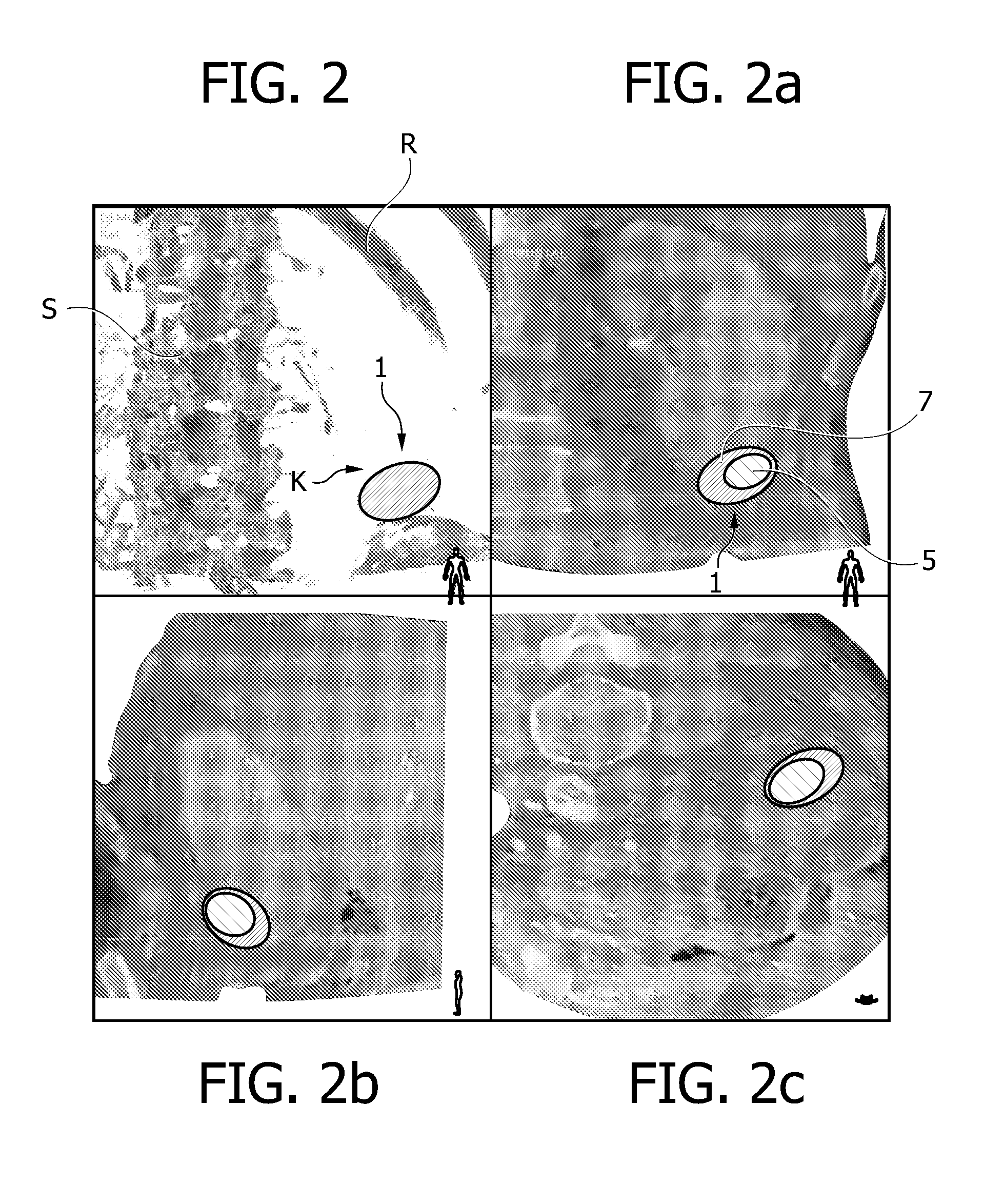
[0035]An ablation treatment planning method according to an embodiment of the present invention will be described with respect to FIGS. 2, 2a, 2b, 2c and 6.

[0036]In FIG. 2, a volume rendered image is shown. Such image may be based on a 3D image data set acquired with an X-ray imaging device from a region of interest. For example, an ablation treatment planning system 100 may comprise such X-ray imaging device such as e.g. a C-arm system as shown in FIG. 6 which is adapted to acquire a plurality of X-ray projection images under various image acquisition angles such that, finally, a 3D image data set may be generated from the plurality of 2D projection images. Therein, an X-ray source 101 attached to a first end of a C-arm 109 may emit X-rays which are transmitted through a region of interest 103 within a patient (not shown) lying on a displaceable table 105. The X-rays are then detected with an X-ray detector 107 attached to a second end of the C-arm 109. Therein, the C-arm may be mo...


PUM


Abstract

An ablation treatment planning and, optionally, guiding method usable for e.g. tumour tissue ablation with a cryoablation needle which cools down an adjacent tumour tissue to thereby generate an ablation volume is proposed. In order to be able to plan an ablation treatment, a 3D image data set of a region of interest may be acquired by e.g. X-ray imaging using e.g. a C-arm system. Then, 3D model data of the ablation volume are introduced into the 3D image data set for example by tagging image pixels using a stencil buffer and possibly by culling specific inside areas and / or outside areas of the ablation volume. Finally, a 2D image to be visualized to a physician and comprising a projection of the region of interest and the ablation volume is drawn wherein an MPR (multi planar reformatting) plane in which the 2D image is drawn is used as a clipping plane. With such graphical approach, an ablation volume having any arbitrary shape such as for example an ellipsoid shape may be visualized within a 3D image space by drawing 2D images in any desired MPR plane such that also oblique orientations of the ablation volume can be represented. In a subsequent guiding procedure, an ablation needle may be guided to a location and in an orientation as previously planned.

Description

FIELD OF THE INVENTION[0001]The present invention relates to an ablation treatment planning method and to an ablation treatment planning and needle guiding method. Furthermore, the present invention relates to devices for performing such methods, to a computer program adapted for controlling such methods when executed on a computer and a computer-readable medium having stored thereon such computer program.BACKGROUND OF THE INVENTION[0002]In order to treat cancer, it may be necessary to remove or destroy tumourous tissue in a body of a patient. Due to advances in imaging technology and the availability of highly controllable medical devices, ablation technology is becoming a viable treatment option for a variety of non-resectable tumours.[0003]Currently, three ablation methods are commonly used:[0004]RFA (radio frequency ablation) is the most commonly used ablation method that kills tumourous tissue by converting radio frequency energy into heat. RFA devices typically come with diame...

Claims


Application Information

Patent Timeline
Patent Type & Authority Applications(United States)
IPC IPC(8): G06K9/00
CPCA61B18/02A61B19/50A61B19/5212A61B2018/0293G06T19/00A61B2019/507A61B2019/524A61B2019/5289G06T7/0012A61B2019/504A61B34/10A61B90/361A61B2034/104A61B2034/107A61B2090/364A61B2090/3762G06T15/40G06T15/503G06T2210/41G06T2219/008G06T2219/028
Inventor MIELEKAMP, PIETER MARIA
Owner KONINKLIJKE PHILIPS ELECTRONICS NV
Why Eureka
Try Eureka