Reversible thermosensitive recording medium and reversible thermosensitive recording member

a recording medium and thermosensitive technology, applied in thermography, printing, duplicating/marking methods, etc., can solve the problems of inability to delete once-recorded images, cracks are more likely to occur, durability decreases, etc., and achieve excellent crack resistance, durability, and head residue resistance.

Active Publication Date: 2012-09-20
RICOH KK
View PDF2 Cites 6 Cited by
  • Summary
  • Abstract
  • Description
  • Claims
  • Application Information

AI Technical Summary

Benefits of technology

[0055]The maximum particle diameter (D100) of the hollow particles is preferably 5 μm to 10 μm, more preferably 6 μm to 9 μm. If the maximum particle diameter (D100) is over 10 μm, the surface roughness could increase, and pinholes could appear when a solid image is printed. If the maximum particle diameter (D100) is less than 5 μm, it becomes difficult to ensure that the hollow particles have a hollow rate of 70% or more, resulting in lower heat sensitivity. When consideration is given only to increasing color optical density, then it is possible to bring about advantageous effects if the hollow rate is 60% or more. However, the reversible thermosensitive recording medium has an erasing process. In particular, according to an erasing method that uses a thermal head, the energy supplied for erasing is extremely smaller than a heat roller method. Therefore, it is necessary to further increase the degree to which the applied energy is effectively used. Accordingly, in order to ensure an erasing optical density with the erasing method that uses a thermal head and an expanded erasing energy region, the hollow rate of the hollow particles used in the under layer is preferably greater than or equal to 70%, more preferably greater than or equal to 80%.
[0056]The ratio (D100 / D50) of the maximum particle diameter (D100) to the 50%-frequency particle diameter (D50) of the hollow particles is preferably 2 to 3, more preferably 2.2 to 2.9. The ratio (D100 / D50) exceeding 3 means that the particle size distribution is in a broad state. In this case, the proportion of fine particles whose particle diameter is less than or equal to 1 μm becomes higher; in the under layer that uses the above particles, the distribution of the hollow particles becomes uneven, possibly leading to a decrease in sensitivity. If the ratio (D100 / D50) is less than 2, the particle size distribution becomes extremely sharp. It is difficult to realize in terms of conditions for the synthesis of the hollow particles.
[0057]In this case, as for the hollow rate of the hollow particles, the particle diameter of the hollow particles is measured, and then the hollow rate is calculated. For example, the hollow particles are embedded in epoxy resin, which is then cut with a microtome. Then, a cut plane is observed under a scanning electron microscope (SEM), the outer diameter and inner diameter of the hollow particles are measured, and the hollow rate is calculated from the following equation 1:Hollow rate(%)=(inner diameter of hollow particles) / (outer diameter of hollow particles)×100
[0058]The particle diameter and particle size distribution of the hollow particles can be measured by, for example, a laser diffraction-type particle size distribution measuring device (manufactured by HORIBA, Ltd., LA-900). The median diameter (D50) is a particle diameter with a frequency of 50%. The maximum particle diameter (D100) is a maximum value of the distribution.
[0059]The hollow particles are preferably made of a vinyl polymer that includes a crosslinked structure as a shell material. The vinyl polymer having a crosslinked structure includes at least one type of vinyl monomer and at least one type of crosslinking monomer.
[0060]The vinyl monomer is not specifically restricted, and can be selected appropriately according to the purpose. For example, the following can be listed: a monomer having carboxylic acid within a molecule, such as acrylic acid ester, ethylene, propylene, vinyl acetate, styrene, acrylonitrile, methacrylonitrile, acrylic acid, methacrylic acid, succinic acid, and itaconic acid; metal carboxylate such as magnesium acrylate, calcium acrylate, zinc acrylate, magnesium methacrylate, calcium methacrylate, and zinc methacrylate; N-methylolacrylamide, N-methylolmetacrylamide, glycidyl acrylate, glycidyl methacrylate, 2-hydroxyethyl(meth)acrylate, 2-hydroxypropyl(meth)acrylate, 2-hydroxybutyl(meth)acrylate, 2-hydroxy-3-phenoxypropylacrylate, N,N-dimethylaminoethyl(meth)acrylate, N,N-dimethylaminopropyl methacrylate, magnesium monoacrylate and zinc monoacrylate, which have, within a molecule, a group reactive to carboxylic acid; acrylamide, methacrylamide, N,N-dimethylacrylamide, N,N-dimethylmethacrylamide, methyl methacrylate, t-butyl methacrylate, isobornyl(meth)acrylate, cyclohexyl methacrylate, benzyl methacrylate, N-vinylpyrrolidone, styrene, N-phenyl maleimide, N-naphthyl maleimide, N-cyclohexyl maleimid, and methyl maleimide.

Problems solved by technology

However, because the coloring thereof is irreversible, it is not possible to delete a once-recorded image and repeatedly use.
The problem with such a reversible thermosensitive recording medium is that, when an under layer is provided between a support and a reversible thermosensitive recording layer, a crack is more likely to occur.
However, since the heat resistance is low, the durability decreases.
Another problem is that residues adhere to a heat source such as a thermal head.
However, even the above proposal does not have performance sufficient enough in terms of all the following properties: durability, crack resistance, and resistance to formation of residue on the head (head-residue resistance).

Method used


Image

  • Reversible thermosensitive recording medium and reversible thermosensitive recording member
  • Reversible thermosensitive recording medium and reversible thermosensitive recording member
  • Reversible thermosensitive recording medium and reversible thermosensitive recording member

Examples


first embodiment

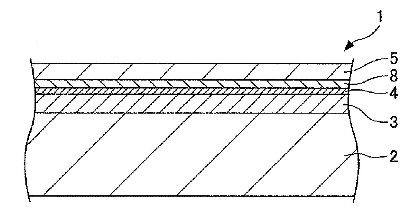
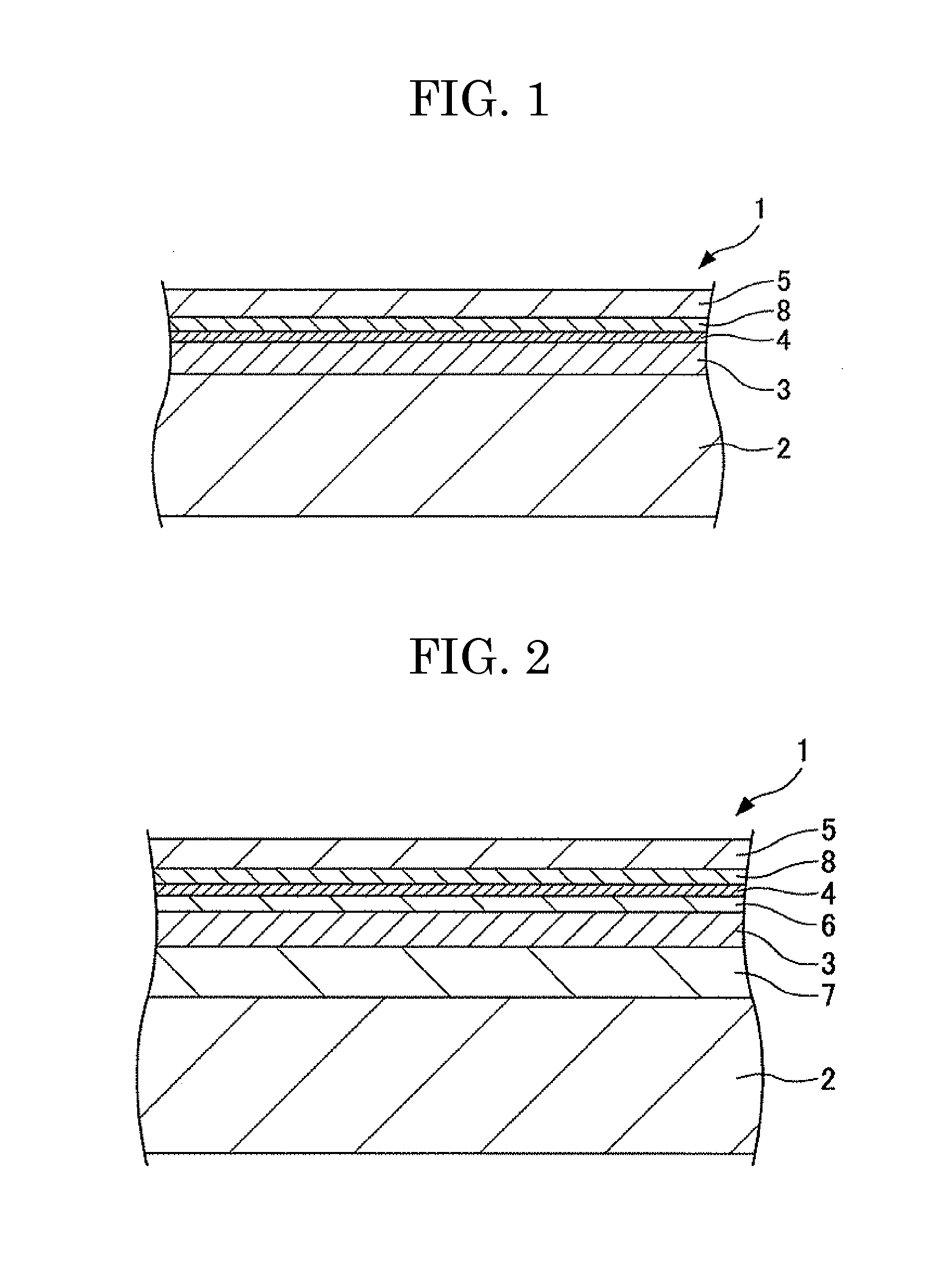
[0234]FIG. 1 shows the configuration of a reversible thermosensitive recording medium according to the first embodiment of the present invention. FIG. 1 is a schematic, partial cross-sectional view showing a reversible thermosensitive recording medium according to the present invention. As shown in FIG. 1, in the reversible thermosensitive recording medium 1, on a surface of a sheet-like support 2, a reversible thermosensitive recording layer 3, a gas barrier layer 4, a primer layer 8, and a protective layer 5 are stacked in that order.

[0235]The reversible thermosensitive recording layer 3 is stacked in such a way that the lower surface of the reversible thermosensitive recording layer 3 is in contact with the support 2 having sufficient gas barrier properties, and the upper surface is covered with the gas barrier layer 4, thereby keeping both surfaces from being in direct contact with the outside air. In principle, all that is required is for the reversible thermosensitive recordin...

second embodiment

[0236]FIG. 2 shows the configuration of a reversible thermosensitive recording medium according to the second embodiment of the present invention. FIG. 2 is a schematic, partial cross-sectional view showing a reversible thermosensitive recording medium according to the present invention. In a reversible thermosensitive recording medium 1 of the second embodiment shown in FIG. 2, an under layer 7, which is high in thermal insulation, is stacked between a reversible thermosensitive recording layer 3 of the reversible thermosensitive recording medium 1 and a support 2.

third embodiment

[0237]The reversible thermosensitive recording medium of the present invention may be attached to another medium via an adhesive layer. Alternatively, a back coat layer may be provided on one side (back surface) of a support such as PET film; on the opposite side of the back coat layer, a release layer that is used in a thermal transfer ribbon may be provided; a reversible thermosensitive recording layer may be provided on the release layer; on a surface, a resin layer capable of transfer onto a resin film or PET film may be further provided; and the transfer may be carried out with a thermal transfer printer. The reversible thermosensitive recording medium of the present invention may be processed into a sheet or card. The reversible thermosensitive recording medium can be processed so as to have an arbitrary shape. Moreover, a printing process may be performed on the top or back surface of the reversible thermosensitive recording medium. When being processed into a card, the rever...


PUM

PropertyMeasurementUnit
elongationaaaaaaaaaa
glass transition temperatureaaaaaaaaaa
elongationaaaaaaaaaa

Abstract

A reversible thermosensitive recording medium including: a support; a reversible thermosensitive recording layer on the support; and a protective layer on the reversible thermosensitive recording layer, wherein the reversible thermosensitive recording layer contains an electron-donating color-forming compound and an electron-accepting compound, wherein the protective layer contains a polyester acrylate resin, and wherein the protective layer has a glass transition temperature of 230° C. or higher and has an elongation of 10% or higher.

Description

BACKGROUND OF THE INVENTION[0001]1. Field of the Invention[0002]The present invention relates to a reversible thermosensitive recording medium and a reversible thermosensitive recording member having the reversible thermosensitive recording medium.[0003]2. Description of the Related Art[0004]Conventionally, the following thermosensitive recording medium has been widely known: the thermosentitive recording medium that uses a color reaction between an electron-donating color-forming compound (also referred to as “color former or leuco dye,” hereinafter) and an electron-accepting compound (also referred to as “developer,” hereinafter). As OA has advanced, the thermosensitive recording medium has become widely used as output paper of facsimile, word processors, and scientific measurement machines, and more recently as magnetic thermosensitive cards such as prepaid cards and point cards. As for such a thermosensitive recording medium in practical use, in terms of environmental concerns, ...

Claims


Application Information

Patent Timeline
Patent Type & Authority Applications(United States)
IPC IPC(8): B41M5/337B41M5/30
CPCB41M5/305B41M5/44B41M2205/38B41M2205/18B41M2205/40B41M2205/04
Inventor TSUCHIMURA, YUARAI, SATOSHIMARUYAMA, JUN
Owner RICOH KK
Why Eureka
Try Eureka