Interspinous process implant and method of implantation

Inactive Publication Date: 2012-09-20
KYPHON
View PDF9 Cites 21 Cited by
  • Summary
  • Abstract
  • Description
  • Claims
  • Application Information

AI Technical Summary

Benefits of technology

[0013]The method of implanting the interspinous process device avoids the need to create a large medial line incision in the patient or the dissection of soft tissue at the affected level. Instead, the interspinous process device may be implanted in a minimally invasive manner. The shaft of the first retention member is inserted through the interspinous ligament, which has been dissected to create an opening therethrough, from one side of the adjacent spinous processes. Dissecting the interspinous ligament allows passage of the shaft of the first retention member therethrough, and through the space between adjacent spinous processes with a lateral approach. The first retention member is oriented such that the major axis of the first retention member is generally parallel to the sagittal and coronal planes and is generally normal to the axial plane. Similarly, the core of the second retention member may be inserted through the interspinous ligament from the other side of the adjacent spinous processes. The second retention member is oriented such that its major axis extends in a direction that is generally parallel to the major axis of the first retention member and the sagittal and coronal planes and is generally normal to the axial plane. The core is inserted into the lumen of the sleeve and the locking mechanism locks the sleeve and the core, and thus the first and second retention members, together. As noted above, the major axes of the first retention member and the second retention member define a dimension that is greater than the distance between adjacent spinous processes. In this manner, the interspinous process device is held in place by the first and second retention members and the shaft prevents the space between the adjacent spinous processes from collapsing during extension of the spine.

Problems solved by technology

The clinical syndrome of neurogenic intermittent claudication due to lumbar spinal stenosis is a frequent source of pain in the lower back and extremities, leading to impaired walking, and causing other forms of disability in the elderly.
With spinal stenosis, the spinal canal narrows and pinches the spinal cord and nerves, causing pain in the back and legs.
Medications such as NSAIDS and other anti-inflammatory medications are often used to alleviate pain, although they are not typically effective at addressing spinal compression, which is the cause of the pain.
The failures associated with a decompressive laminectomy may be related to postoperative iatrogenic spinal instability.
However, spinal fusion sacrifices normal spinal motion and may result in increased surgical complications.
It is also believed that fusion to treat various spinal conditions may increase the biomechanical stresses imposed on the adjacent segments.
The resultant altered kinematics at the adjacent segments may lead to accelerated degeneration of these segments.
For example, where the spacer portion of the implant is formed from a hard material to maintain distraction between adjacent vertebrae, point loading of the spinous process can occur due to the high concentration of stresses at the point where the hard material of the spacer contacts the spinous process.
This may result in excessive subsidence of the spacer into the spinous process.
In addition, if the spinous process is osteoporotic, there is a risk that the spinous process could fracture when the spine is in extension.
In addition, because of the human anatomy and the complex biomechanics of the spine, some currently available interspinous process devices may not be easily implantable.
This is because the configuration of such implants makes it difficult to insert the implant laterally into the interspinous space because the spinous processes limit the vertical height of the device that can be implanted laterally into the interspinous space.
It is possible that cutting the supraspinous ligament may compromise the adjacent segment kinematics.

Method used


Image

  • Interspinous process implant and method of implantation
  • Interspinous process implant and method of implantation
  • Interspinous process implant and method of implantation

Examples


Embodiment Construction

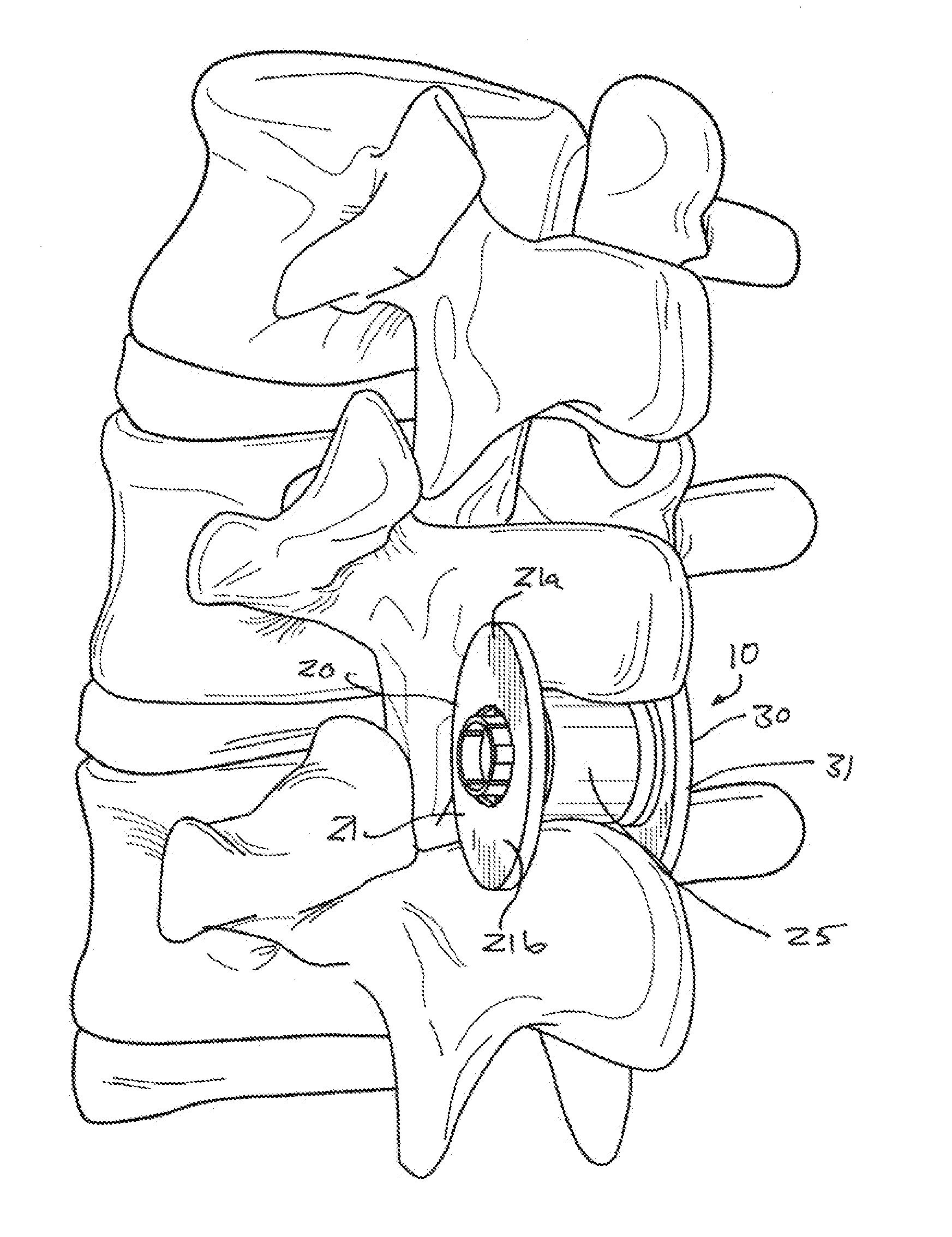
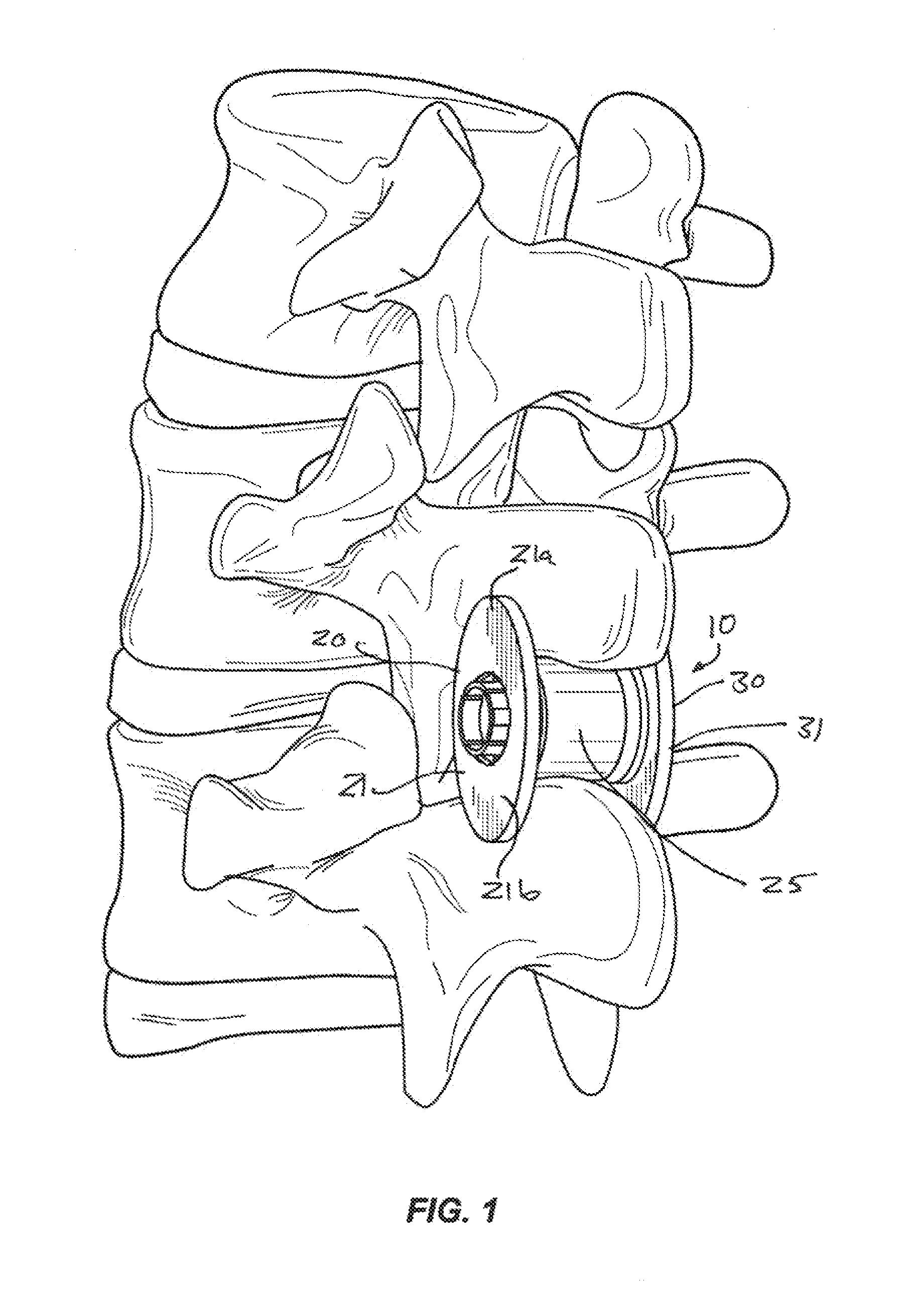
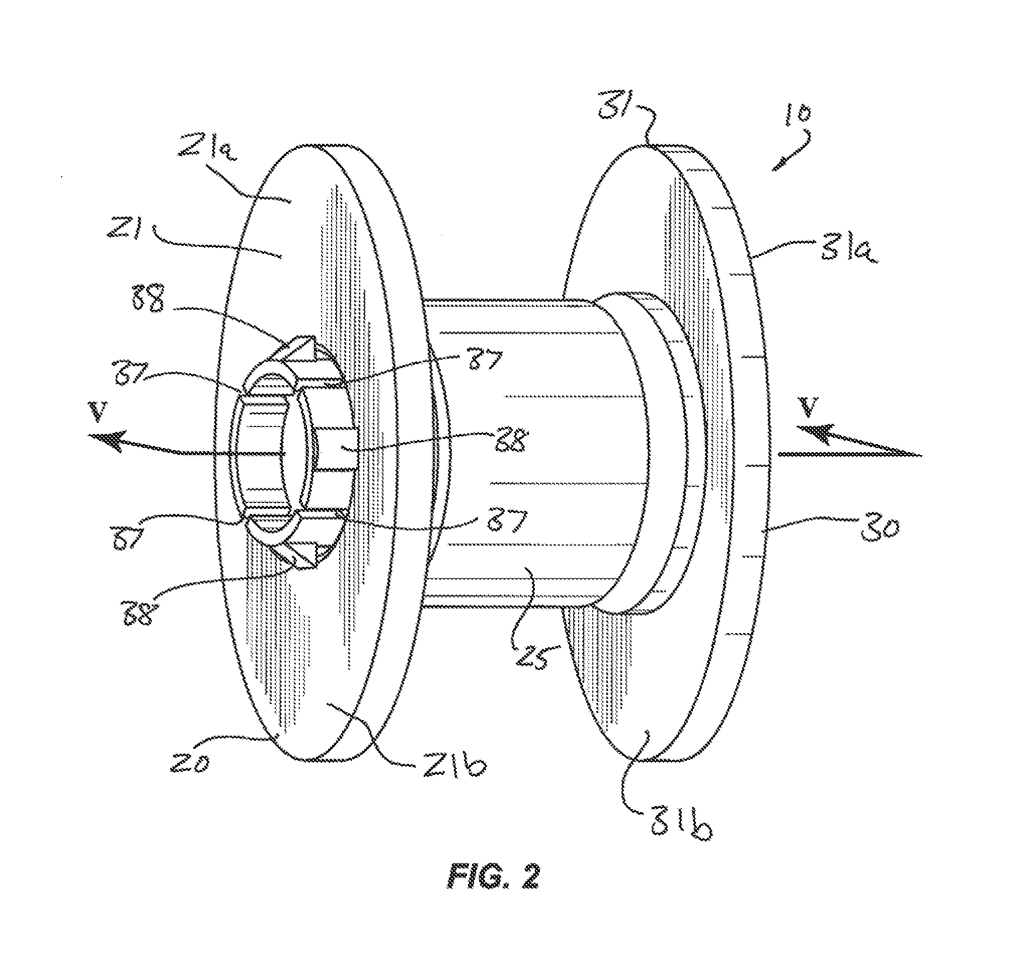
[0019]As used in this specification and the appended claims, the singular forms “a,”“an” and “the” include plural referents unless the context clearly dictates otherwise. Thus, for example, the term “a member” is intended to mean a single member or a-combination of members, and “a material” is intended to mean one or more materials, or a combination thereof. Typically, the words “proximal” and “distal” refer to directions or locations closer to and away from, respectively, an operator (e.g., surgeon, physician, nurse, technician, etc.) who would insert the medical device into the patient, with the tip-end (i.e., distal end) of the device inserted inside a patient's body first. Thus, for example, the device end first inserted inside the patient's body would be the distal end of the device, while the device end last to enter the patient's body would be the proximal end of the device. However, for the device described herein, “distal” refers to a location toward the left in the FIGS. a...


PUM


Abstract

Medical devices for the treatment of spinal conditions are described herein. The medical device includes a sleeve, and optionally a bumper, that is disposed between adjacent spinous processes and has a first retention member and a second retention member, which may be locked together.

Description

BACKGROUND[0001]This invention relates generally to devices for the treatment of spinal conditions, and more particularly, to the treatment of various spinal conditions that cause back pain. Even more particularly, this invention relates to devices that may be placed between adjacent spinous processes to treat various spinal conditions. For example, spinal conditions that may be treated with these devices may include spinal stenosis, degenerative disc disease (DDD), disc herniations and spinal instability, among others.[0002]The clinical syndrome of neurogenic intermittent claudication due to lumbar spinal stenosis is a frequent source of pain in the lower back and extremities, leading to impaired walking, and causing other forms of disability in the elderly. Although the incidence and prevalence of symptomatic lumbar spinal stenosis have not been established, this condition is the most frequent indication of spinal surgery in patients older than 65 years of age.[0003]Lumbar spinal ...

Claims


Application Information

Patent Timeline
IPC IPC(8): A61B17/70
CPCA61B17/7068
Inventor DRUMA, CALINCHABANSKY, BRUCE
Owner KYPHON
Why Eureka
Try Eureka