Method and Apparatus for Fault Injection

Inactive Publication Date: 2012-09-20
EIGENIX
View PDF7 Cites 27 Cited by
  • Summary
  • Abstract
  • Description
  • Claims
  • Application Information

AI Technical Summary

Problems solved by technology

High energy sub-atomic particles occasionally hit integrated circuit (IC) devices and cause interference.
An SEU typically does not permanently affect the device and the device will continue to o

Method used


Image

  • Method and Apparatus for Fault Injection
  • Method and Apparatus for Fault Injection
  • Method and Apparatus for Fault Injection

Examples


Embodiment Construction

[0035]The present invention generally relates to circuits for injecting faults into a larger circuit. Fault injection can be useful because it provides information about the susceptibilities of a circuit to, among other things, single event upsets (SEUs). For example, where certain naturally induced SEUs may occur with low frequency, they may nonetheless, have a dramatic effect on a circuit. Whereas tools exist for bombarding a circuit with high frequency radiation so as to simulate an accelerated lifetime of a circuit, such tools can be expensive and time-consuming. The present invention therefore provides circuits by which faults can be injected so as to test larger circuits vulnerabilities to SEU.

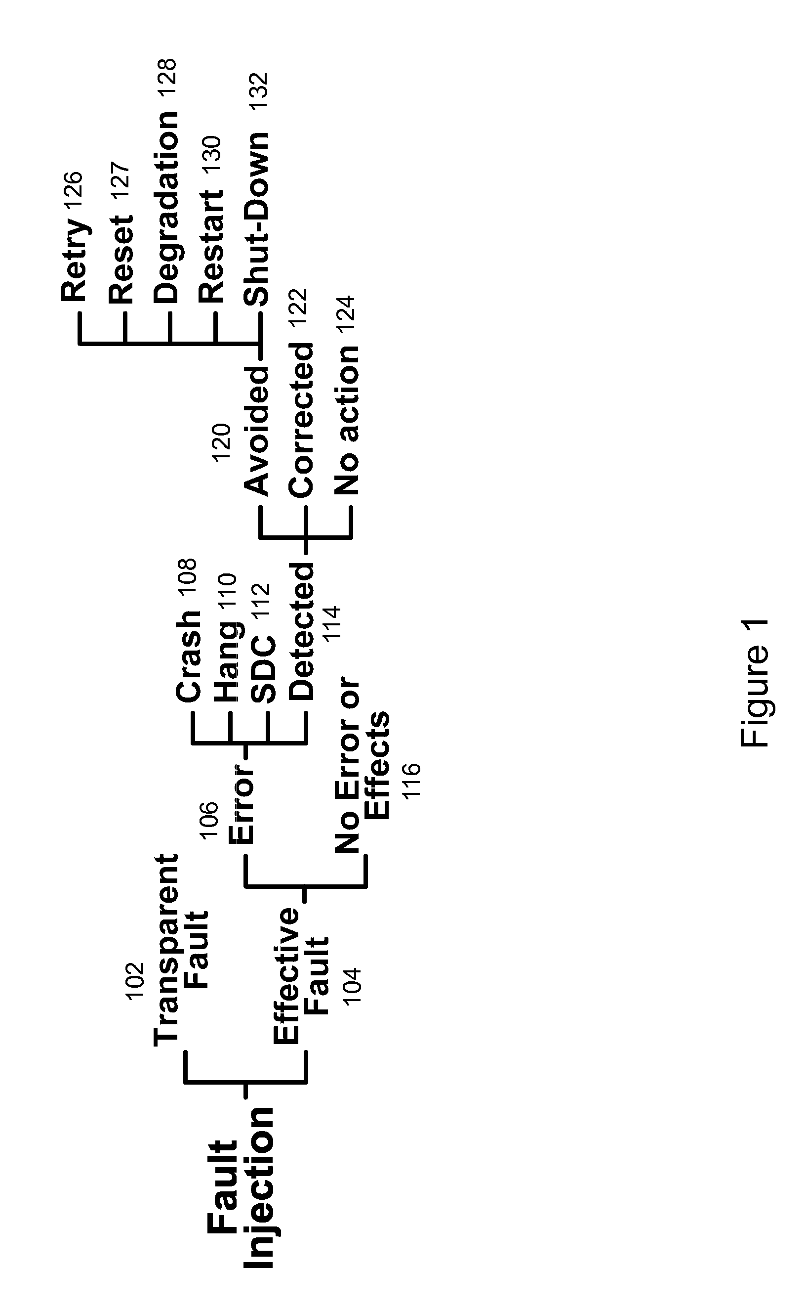
[0036]Fault Injection and Resulting CUT Behavior

[0037]Shown in FIG. 1 are the various types of fault effects that are a result of faults injected into a circuit according to an embodiment of the present invention and the corresponding responses from a circuit under test (CUT) while the C...


PUM


Abstract

The present invention provides various circuits for injecting faults into a larger circuit, sometimes called circuit under test, or CUT. One type of fault injection circuit is a clock controlled fault injection circuit. This type of circuit uses internal scan chains as a way by which a fault injection operation is performed while a system clock is in the off state. Another type of fault injection circuit is a concurrent fault injection circuit. This type of fault injection circuit uses dedicated fault injection scan chains in parallel with or without internal scan chains. Yet another type of fault injection circuit is a hybrid fault injection circuit that uses both clock controlled and concurrent fault injection circuits. Other embodiments are disclosed and still other embodiments would be obvious to those of ordinary skill in the art upon understanding the full scope of the present disclosure.

Description

FIELD OF THE INVENTION[0001]The present invention generally relates to the field of circuit testing. More particularly, the present invention relates to fault injection and scan operation.BACKGROUND OF THE INVENTION[0002]High energy sub-atomic particles occasionally hit integrated circuit (IC) devices and cause interference. When an energetic particle hits an IC chip it may ionize an atom within the circuitry and thereby cause a single event effect to occur. There are several types of single event effects that can occur. The more severe effects include single event burnout and single event latchup. A less severe type of single event effect is a single event upset (SEU).[0003]An SEU is a change of state or a transient pulse through an IC device caused by an ionizing particle. An SEU will manifest itself either by flipping the state of a sequential logic component (such as a memory or a flip-flop), commonly referred to as a “bit flip,” or by introducing a transient pulse through a cir...

Claims


Application Information

Patent Timeline
IPC IPC(8): G01R31/303G06F11/16
CPCG01R31/318547G01R31/318536
Inventor CHUNG, SUNG SOO
Owner EIGENIX
Why Eureka
Try Eureka