Control of fluid flow during treatment of subterranean sites using well fluid injection

a technology of fluid flow and subterranean sites, applied in fluid removal, chemistry apparatus and processes, borehole/well accessories, etc., can solve problems such as reducing the sweep efficiency of water, and achieve the effect of improving oil recovery

Inactive Publication Date: 2012-09-27
EI DU PONT DE NEMOURS & CO
View PDF22 Cites 9 Cited by
  • Summary
  • Abstract
  • Description
  • Claims
  • Application Information

AI Technical Summary

Benefits of technology

[0011]wherein oil r

Problems solved by technology

One problem commonly encountered with water flooding operations is that the heterog

Method used


Image

  • Control of fluid flow during treatment of subterranean sites using well fluid injection

Examples


example 1

Prophetic

To Determine Breakthrough Times in Production Wells

[0033]The breakthrough time for each production well is determined using a tracer chemical such as a sodium salt of Fluorescein dye, commonly known as Uranine (CAS 518-47-8, Part number A833-500, Fisher Scientific, 2000 Park Lane Drive, Pittsburgh, Pa. 15275).

[0034]Uranine (2.7 kilogram, kg) is added to a tank containing 9,000 L of water. The normal flow of injection water to the injection well to be tested is shut off. The Uranine treated water is injected over a 7.2 hours (h) period into the injection well at a rate of injection equal to 1,250 L / h which is the normal injection flow rate. Upon completion of the injection of the 9,000 L of Uranine solution, the normal injection flow of water is restored at the normal injection rate of 30,000 L / D. After the start of Uranine injection, samples are taken from the associated production wells at various time intervals for example, 6, 12, 18, 24, 36, 48 h following initial tracer...

example 2

Prophetic

To Inoculate a Subterranean Site without Loss of Microbial Inoculum

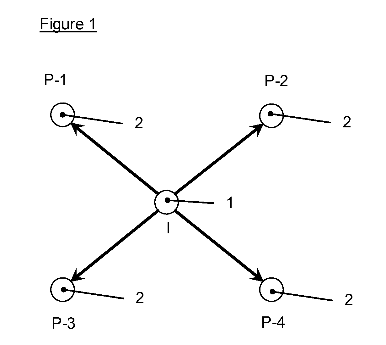
[0035]In this example, the injection and production wells of a subterranean site are arranged in an inverted five spot pattern as shown in FIG. 1. For the purposes of this example, it is assumed that production well P2 has the shortest breakthrough time followed by production well P4 with the second shortest breakthrough time. A microbial inoculum suspension is prepared by making in a 6,000 L tank a nutritional chemical fluid appropriate for the particular microorganism used. A microbial inoculum is then added to the nutritional chemical fluid to produce a suspension at the desired concentration of microbes and nutrients.

The following steps are then taken:

1) Shut off the normal injection water flow into injection well.

2) Inject the inoculum suspension into the injection well at the normal injection rate for the injection well (i.e., 1,250 L / h for 4.8 h)

3) After start of injection of inoculum into the injecti...


PUM


Abstract

Disclosed herein is a method to control distribution of injected microorganisms, nutrients or other chemical treatment fluids from a single injection well to multiple production wells. The sweep efficiency is improved preventing premature production of fluids from production wells with short breakthrough times. This is a useful technique for treatment of subterranean target sites for practice of Microbial Enhanced Oil Recovery and bioremediation.

Description

[0001]This application claims the benefit of U.S. Provisional Application 61 / 387,494, filed Sep. 29, 2010.FIELD OF INVENTION[0002]This disclosure relates to the field of enhanced oil recovery or bioremediation. More specifically, it relates to controlling flow of treatment fluids and / or microorganisms into subterranean strata to enhance oil recovery or bioremediation.BACKGROUND OF THE INVENTION[0003]Primary techniques used in oil recovery which utilize only the natural forces present at an oil well site allow recovery of only a minor portion of the crude oil present in an oil reservoir. Oil well sites are locations where wells have been drilled into a subterranean stratum, containing oil, with the intent to produce oil from that stratum. An oil reservoir typically refers to a deposit of subterranean oil in a subterranean stratum. Secondary oil recovery methods, such as water flooding, that is injection of water through injection wells into the oil reservoir, have been used to force ...

Claims


Application Information

Patent Timeline
IPC IPC(8): E21B43/22
CPCE21B43/20C09K8/582
Inventor ALSOP, ALBERT W.JACKSON, SCOTT CHRISTOPHER
Owner EI DU PONT DE NEMOURS & CO
Why Eureka
Try Eureka