Aerial Work Platforms and Aerial Work Platform Assemblies Comprised of Polymerized Cycloolefin Monomers

Inactive Publication Date: 2012-09-27
EAKIN GEORGE R +1
View PDF4 Cites 26 Cited by
  • Summary
  • Abstract
  • Description
  • Claims
  • Application Information

AI Technical Summary

Benefits of technology

[0075]In providing long gel times for the norbornene functional monomers, it is known to react these alkylaluminum compounds with branched or hindered alcohols and to use combinations of such alcohols with unhindered alcohols. The use of compounds containing an acetylene moiety including without limitation 4-octyne or phenylacetylene may also be used to control the reactivity of the catalysts thereby providing extended gel times. The hindered alcohols include tertiary alcohols, secondary hindered alcohols and primary hindered alcohols. When such alcohols are combined with unhindered alcohols the temperature necessary to initiate gel in the reactive formulation is reduced. Specific examples of hindered secondary alcohols include 2,4-dimethyl-3-pentanol, 3,5-dimethyl-4-heptanol and 2,4-diethyl-3-hexanol and the like. Specific examples of hindered primary alcohols include neopentyl alcohol, 2,2-dimethyl-1-butanol, 2,2-diethyl-1-butanol and the like. Specific examples of suitable tertiary alcohols include t-butanol, t-amylalcohol, 3-ethyl-3-pen

Problems solved by technology

Conventional thermoset materials, including without limitation epoxy, epoxy vinyl ester, polyester, vinyl ester, silicone, phenolic and polyurethane, have relatively high dielectric losses and high dielectric constants, which are not desirable for aerial devices including without limitation aerial work platforms and aerial work platform assemblies.
In addition, as noted above, aerial work platforms and aerial work platform assemblies constructed from such conventional thermoset materials requires the use of fiber reinforcement to provide the necessary structural strength, as such thermoset materials without fiber reinforcement are not ab

Method used


Image

  • Aerial Work Platforms and Aerial Work Platform Assemblies Comprised of Polymerized Cycloolefin Monomers
  • Aerial Work Platforms and Aerial Work Platform Assemblies Comprised of Polymerized Cycloolefin Monomers
  • Aerial Work Platforms and Aerial Work Platform Assemblies Comprised of Polymerized Cycloolefin Monomers

Examples


Example

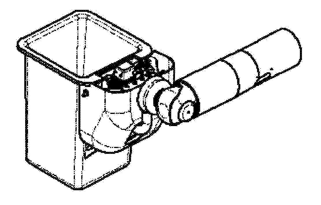
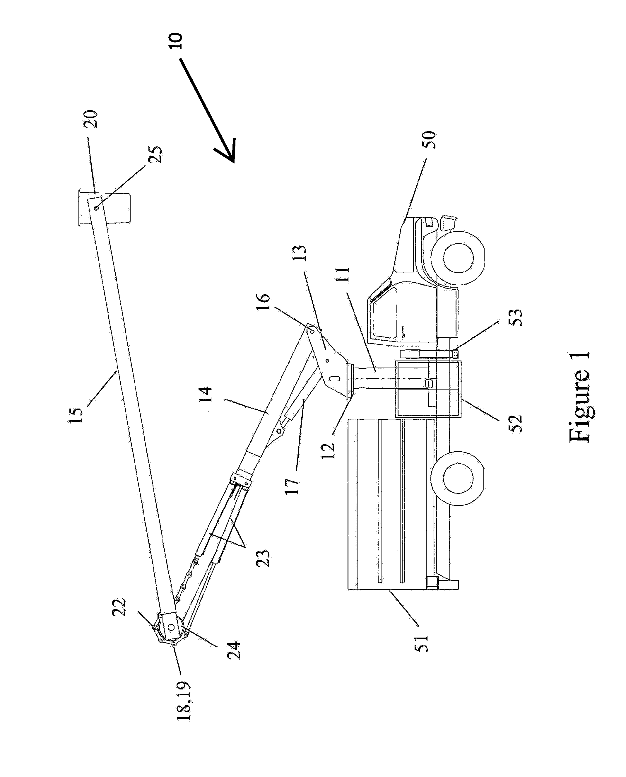
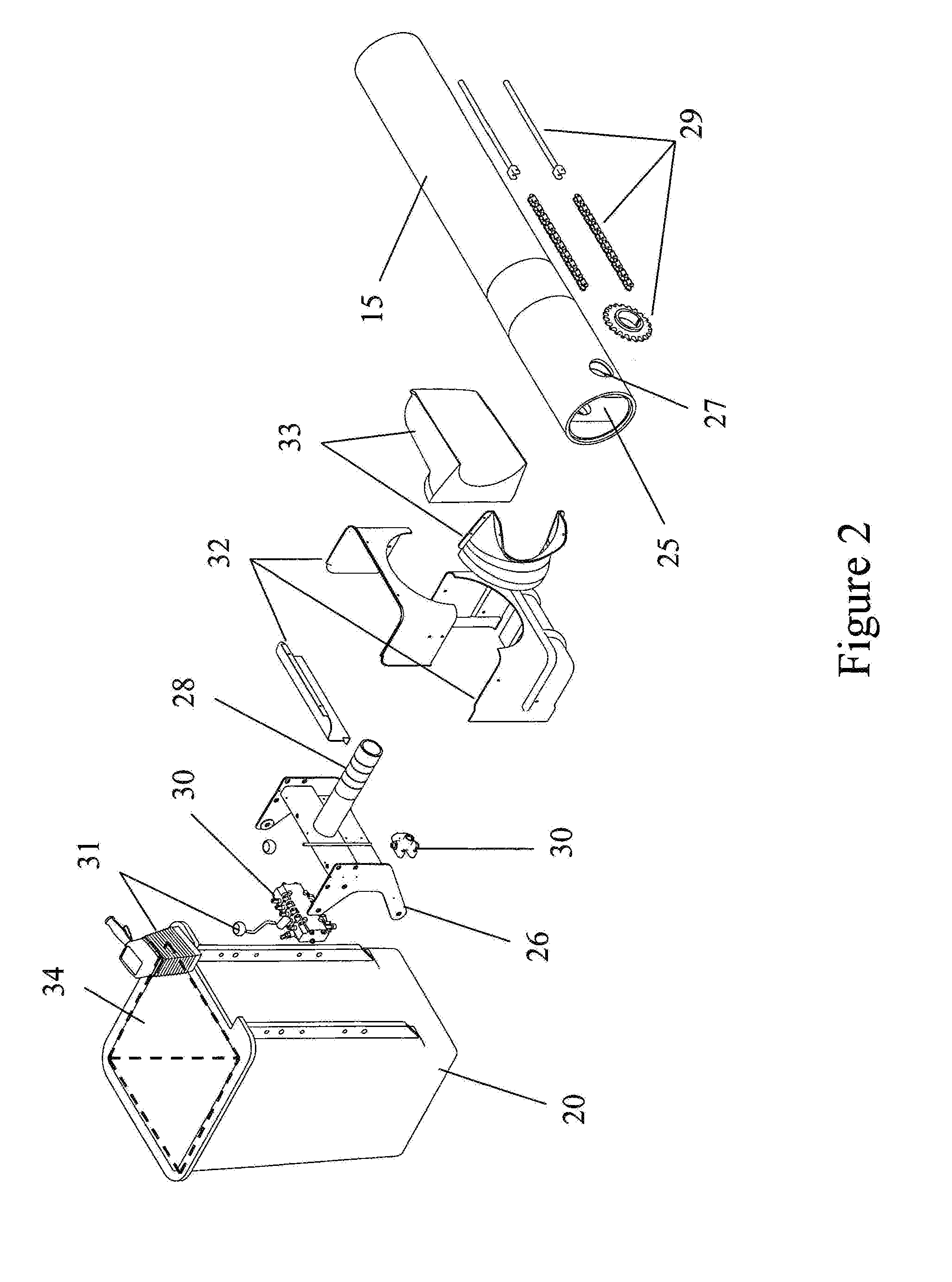
[0224]Certain features, which are used in assembling or operating the invention, but which are known to those of ordinary skill in the art and not bearing upon points of novelty, such as screws, bolts, nuts, welds, and other common fasteners, may not be shown for clarity. In order to appreciate the novelty of the present invention and its improvements over prior designs, a detailed description of the existing art is provided first with reference to FIGS. 1 and 2, followed by a description of various embodiments of the invention. The following description of FIGS. 1 and 2 focuses on one prior art configuration, particularly an over-center machine with an articulation linkage, with the understanding that many other variations of aerial configurations may be equally suitable for use with the invention including without limitation overcenter, non-overcenter, telescopic, and telescopic articulating.

[0225]Referring now to the drawings in more detail and specifically to FIG. 1, an articula...


PUM


Abstract

An aerial work platform assembly includes: a) a platform shaft retaining assembly; b) a mounting bracket connected to the platform shaft retaining assembly; and c) a platform connected to the mounting bracket. The platform shaft retaining assembly includes two concentric apertures for installation of a pivot shaft therein; the mounting bracket having an upper gusset member and a center gusset member that are bonded together and that include horizontal portions to which the pivot shaft is bonded; upper and lower platform pins; a valve bracket; a platform bracket; and upper platform pins that provide for pivoting on a lower platform pin and tilting down of the platform thereby. At least one of the platform shaft retaining assembly, the mounting bracket, the platform, the upper and lower platform pins, and the valve bracket are molded from at least one monomer having at least one norbornene functionality, such as polydicyclopentadiene.

Description

RELATED APPLICATIONS[0001]This application claims priority of U.S. Provisional Application No. 61 / 467,785 filed on Mar. 25, 2011. The entire content of this prior application is incorporated herein by reference.BACKGROUND OF THE INVENTION[0002]Aerial Devices and Aerial Work Platforms and Aerial Work Platform Assemblies are known and are described in U.S. Pat. Nos. 2,954,092; 3,005,512; 3,022,854; 3,087,581; 3,139,948; 3,146,853; 3,159,240; 3,169,602; 3,233,700; 3,295,633; 3,404,751; 3,414,079; 3,554,319; 3,590,948; 3,605,941; 3,625,305; 4,047,593; 4,160,492; 4,334,594; 4,553,632; 4,763,755; 4,763,758; 4,883,145; 5,460,246; 5,722,505; 5,944,138; and 7,748,496, the contents of each of which are included herein by reference in their entirety. Aerial Work Platforms and Aerial Work Platform Assemblies are also known and are described in U.S. patent application Ser. Nos. 11 / 055,346; 12 / 284,572; and 12 / 761,836, the contents of each of which are included herein by reference in their entiret...

Claims


Application Information

Patent Timeline
IPC IPC(8): B66F11/04
CPCB66F11/044B29C37/0032C08G61/08C08G2261/3324C08G2261/418B29C2037/0035
Inventor EAKIN, GEORGE R.MOORE, JASON L.
Owner EAKIN GEORGE R
Why Eureka
Try Eureka