Antenna Module

Active Publication Date: 2012-09-27
MEDIATEK INC
View PDF6 Cites 29 Cited by
  • Summary
  • Abstract
  • Description
  • Claims
  • Application Information

AI Technical Summary

Benefits of technology

[0007]In the embodiment of the invention, four ground points are utilized to improve impedance matching effect. The first parasitic arm couples with the second section of the radiator to increase wideband coverage of the antenna module to 850 GHz. The second parasitic arm couples with the first section of the radiator to increase wideband coverage of the antenna module to 1900 MHz and 2100 MHz. The length of the first parasitic arm is shorter than a quarter of the wavelength of the signal at 850 GHz. The impedance matching unit improves impedance matching

Problems solved by technology

A conventional dielectric antenna module is expens

Method used


Image

  • Antenna Module
  • Antenna Module
  • Antenna Module

Examples


Example

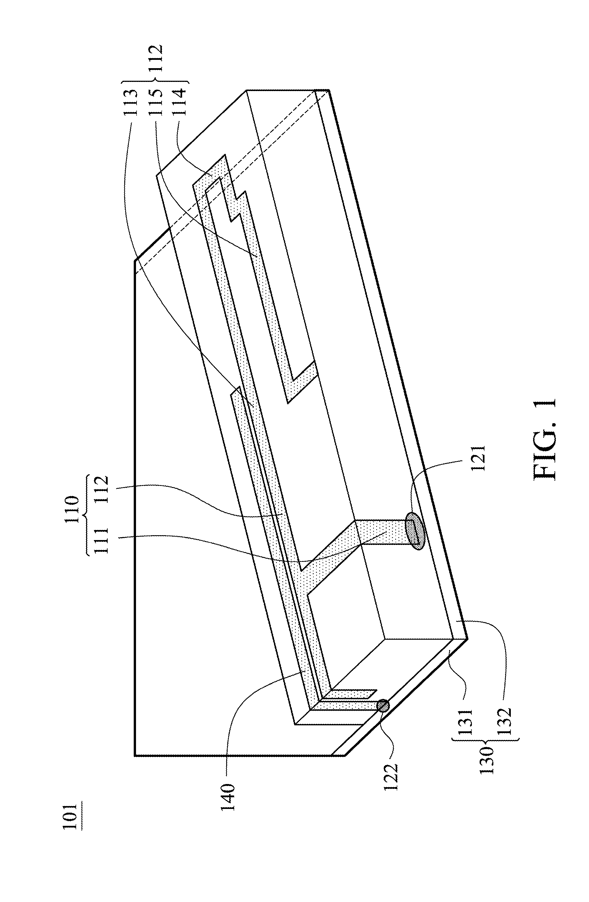
[0016]FIG. 1 shows an antenna module 101 of a first embodiment of the invention. The antenna module 101 includes a radiator 110, a feed pin 121, a ground element 130 and a first parasitic arm 140. The radiator 110 comprises a first section 111 and a second section 112, wherein an end of the first section 111 is connected to the second section 112, and the section 111 is perpendicular to the second section 112. The feed pin 121 is connected to another end of the first section 111. The first parasitic arm 140 is parallel and adjacent to at least portion of the second section 112, wherein an end of first parasitic arm 140 is connected to the ground element 130 at a ground point 122, and the first parasitic arm 140 couples with the second section 112 of the radiator 121.

[0017]In this embodiment, the ground element 130 is planar, and the ground element 130 comprises a first side 131 and a second side 132, and the first side 131 is perpendicular to the second side 132, and the first paras...

Example

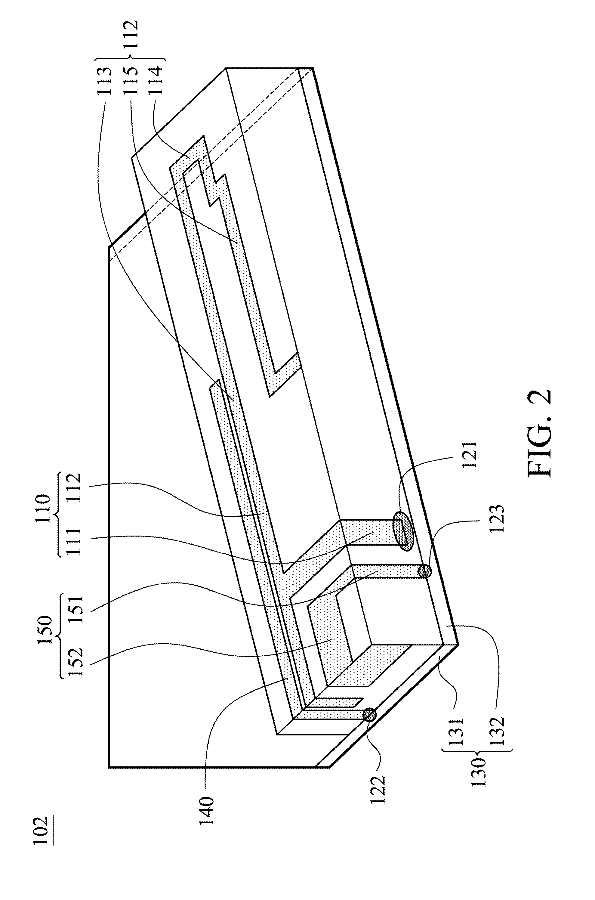
[0019]FIG. 2 shows an antenna module 102 of a second embodiment of the invention. The antenna module 102 includes a radiator 110, a feed pin 121, a ground element 130, a first parasitic arm 140 and a second parasitic arm 150. The radiator 110 comprises a first section 111 and a second section 112, wherein an end of the first section 111 is connected to the second section 112. The feed pin 121 is connected to another end of the first section 111. The first parasitic arm 140 is parallel and adjacent to at least portion of the second section 112, wherein an end of first parasitic arm 140 is connected to the ground element 130 at a ground point 122, and the first parasitic arm 140 couples with the second section 112 of the radiator 121. The second parasitic arm 150 is partially parallel to the first section 111, and the second parasitic arm 150 couples with the first section 111 of the radiator 110, and an end of the second parasitic arm 150 is connected to the ground element 130 at ano...

Example

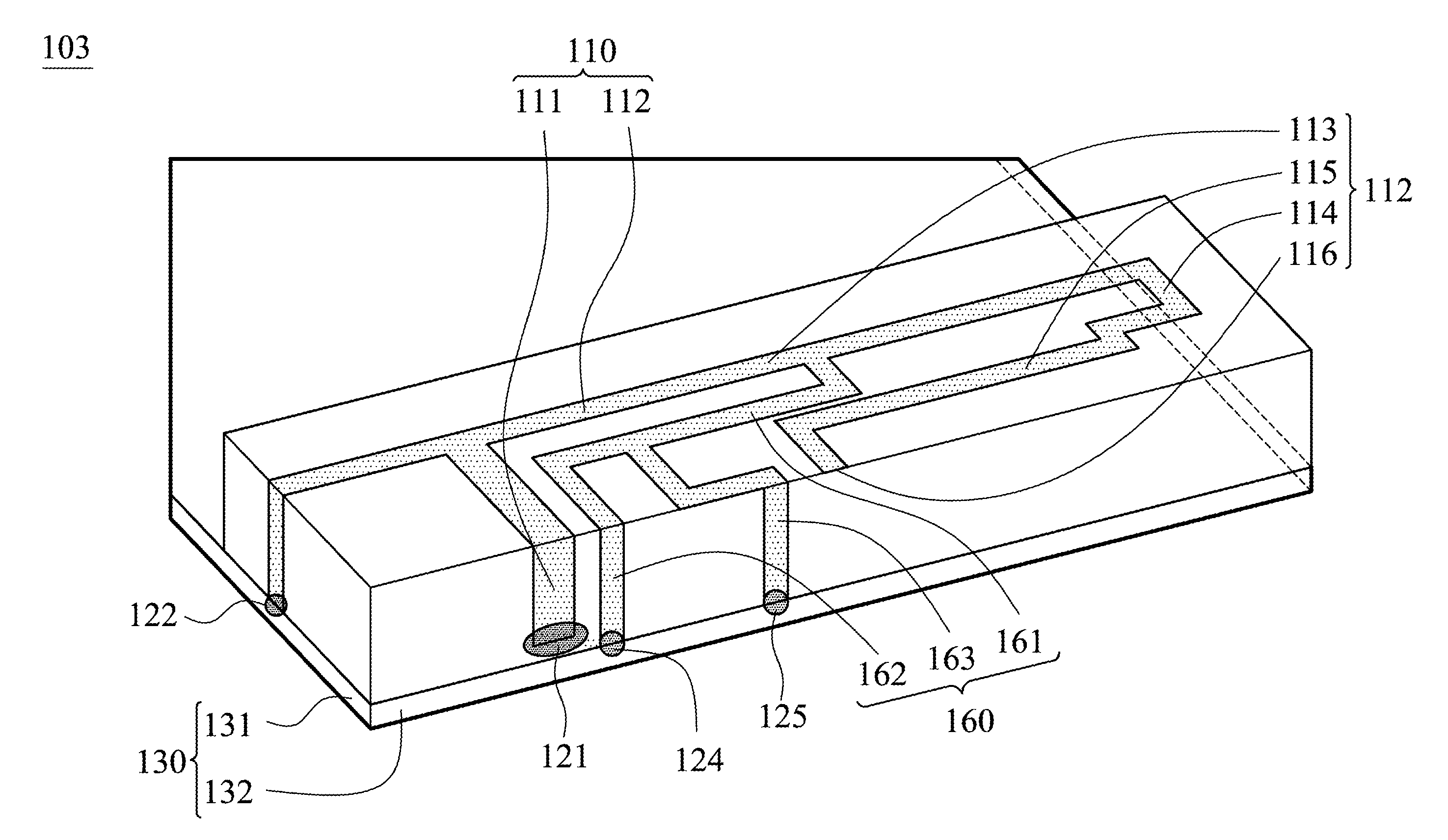
[0024]FIG. 3 shows an antenna module 103 of a third embodiment of the invention. The antenna module 103 includes a radiator 110, a feed pin 121, a ground element 130, and an impedance matching unit 160. The radiator 110 comprises a first section 111 and a second section 112, wherein an end of the first section 111 is connected to the second section 112. The feed pin 121 is connected to another end of the first section 111. The impedance matching unit 160 is connected to the second section 112 and the ground element 130.

[0025]The impedance matching unit 160 comprises a first matching section 161, a second matching section 162 and a third matching section 163, and the first matching section 161 is connected to the second section 112 of the radiator 110, and the second matching section 162 is connected to the first matching section 161 and the ground element 130, and the third matching section 163 is connected to the first matching section 161 and the ground element 130. The second mat...


PUM


Abstract

An antenna module is provided. The antenna module includes a radiator, a feed pin, a ground element, a first parasitic arm, a second parasitic arm and an impedance matching unit. The radiator includes a first section and a second section, wherein an end of the first section is connected to the second section, and the first section is perpendicular to the second section. The feed pin is connected to another end of the first section. The first parasitic arm is parallel to the second section, wherein an end of first parasitic arm is connected to the ground element, and the first parasitic arm couples with the second section of the radiator. The impedance matching unit is connected to the second section and the ground element. The second parasitic arm is partially parallel to the first section, and the second parasitic arm couples with the first section of the radiator, and an end of the second parasitic arm is connected to the ground element.

Description

BACKGROUND OF THE INVENTION[0001]1. Field of the Invention[0002]The present invention relates to an antenna module, and in particular relates to a Penta-band antenna module.[0003]2. Description of the Related Art[0004]Nowadays, mobile devices require multi-mode and multi-band communication functions, and need to transmit wireless signals of frequency bands such as GSM850 / 900 / 1800 / 1900 / UMTS (Penta-band), where GSM and UMTS are the abbreviations of Global System for Mobile Communications and the Universal Mobile Telecommunications System, respectively.[0005]Conventionally, a dielectric antenna module is utilized to transmit wireless signals of frequency bands such as GSM850 / 900 / 1800 / 1900 / UMTS (Penta-band). A conventional dielectric antenna module includes a Planar Inverted F Antenna (PIFA) radiator and a dielectric radiator. The PIFA radiator is utilized to transmit wireless signals of frequency bands such as GSM800 / 900, and the dielectric radiator is utilized to transmit wireless sig...

Claims


Application Information

Patent Timeline
IPC IPC(8): H01Q19/02H01Q1/50H01Q5/10H01Q5/371H01Q5/378
CPCH01Q1/243H01Q5/378H01Q5/371H01Q9/42
Inventor HSIEH, SHIH-WEIFANG, SHYH-TIRNG
Owner MEDIATEK INC
Why Eureka
Try Eureka