
Control Methods for Parallel-Connected Power Converters

a technology of power converters and control methods, applied in power conversion systems, ac-dc conversion without reversal, electrical apparatus, etc., can solve problems such as adverse effects on voltage regulation performan

Inactive Publication Date: 2012-09-27
GE ENERGY POWER CONVERSION TECH
View PDF4 Cites 18 Cited by
  • Summary
  • Abstract
  • Description
  • Claims
  • Application Information

AI Technical Summary

Benefits of technology

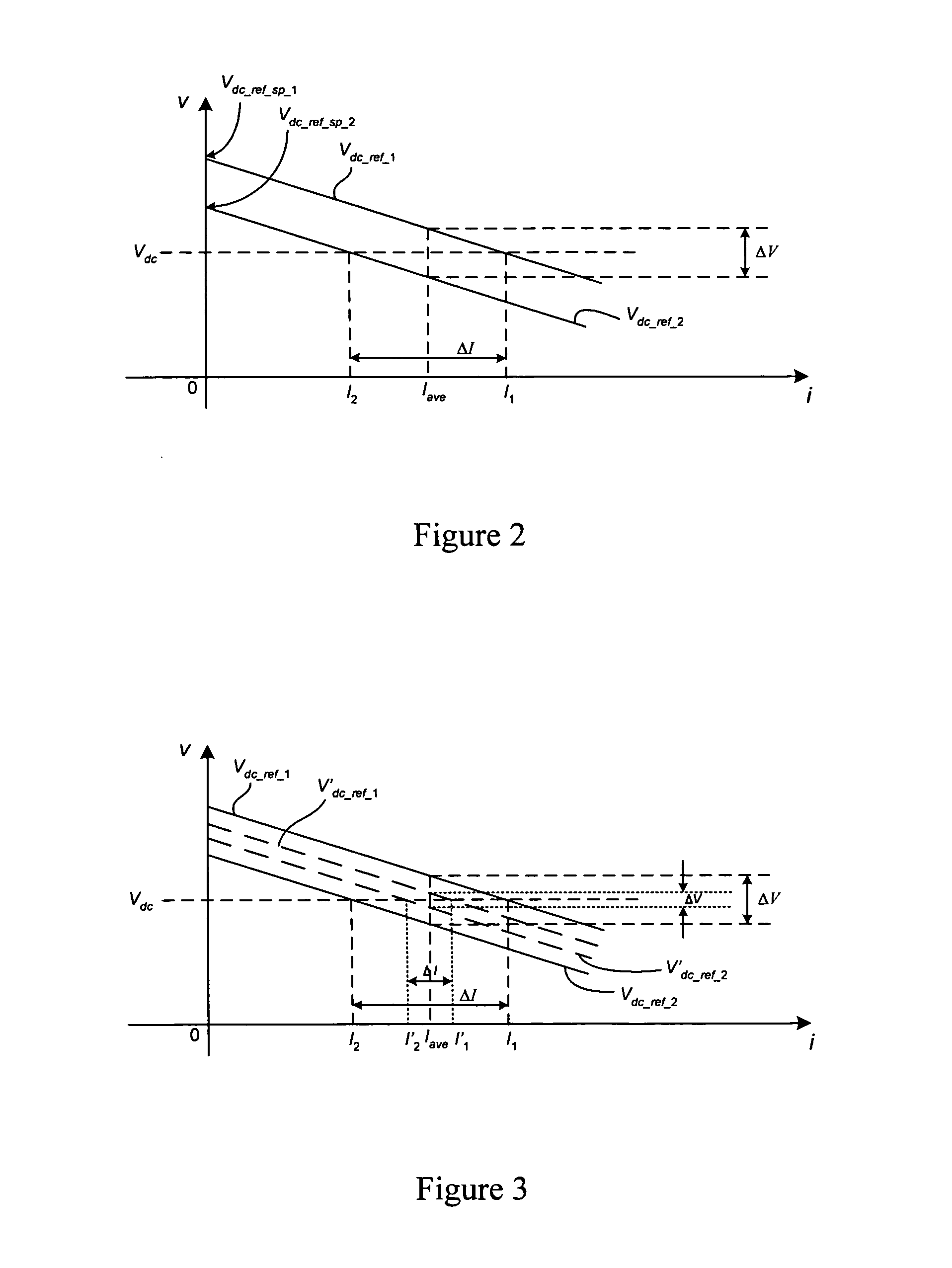
[0014]The method enables the current sharing performance of the power converters to be improved and at the same time enables the voltage regulation performance to be improved. This is in contrast to some known voltage droop control methods in which the voltage regulation performance is adversely affected as current sharing performance is improved.
[0050]The PWM strategy of each power converter may be defined by an independent voltage carrier signal and an independently controllable modulating sinusoidal voltage signal which are used to generate a PWM command signal for each PWM strategy. The voltage carrier signals of the PWM strategies may have the same switching period and desynchronisation of the PWM command signals may cause an unwanted circulating current to flow between the power converters. Accordingly, at least one of the plurality of parallel-connected power converters may include a controller which is selectively operable to provide the independently controllable modulating sinusoidal voltage signal of the PWM strategy of the at least one power converter with a dc voltage offset to modify the PWM command signal of the at least one power converter. This may increase the synchronisation of the PWM command signals so that the magnitude of any unwanted circulating current is reduced.

Problems solved by technology

This is in contrast to some known voltage droop control methods in which the voltage regulation performance is adversely affected as current sharing performance is improved.

Method used


Image

  • Control Methods for Parallel-Connected Power Converters
  • Control Methods for Parallel-Connected Power Converters
  • Control Methods for Parallel-Connected Power Converters

Examples


Embodiment Construction

[0060]Embodiments of the present invention will now be described by way of example only and with reference to the accompanying drawings.

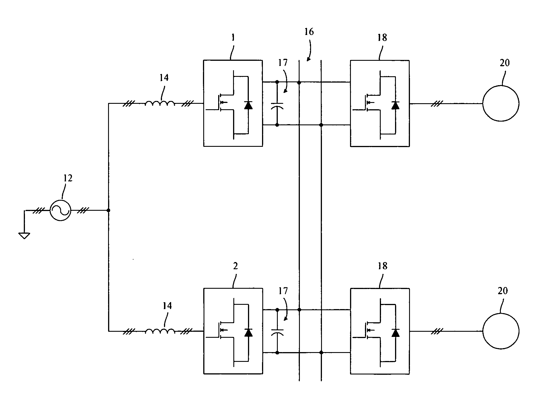
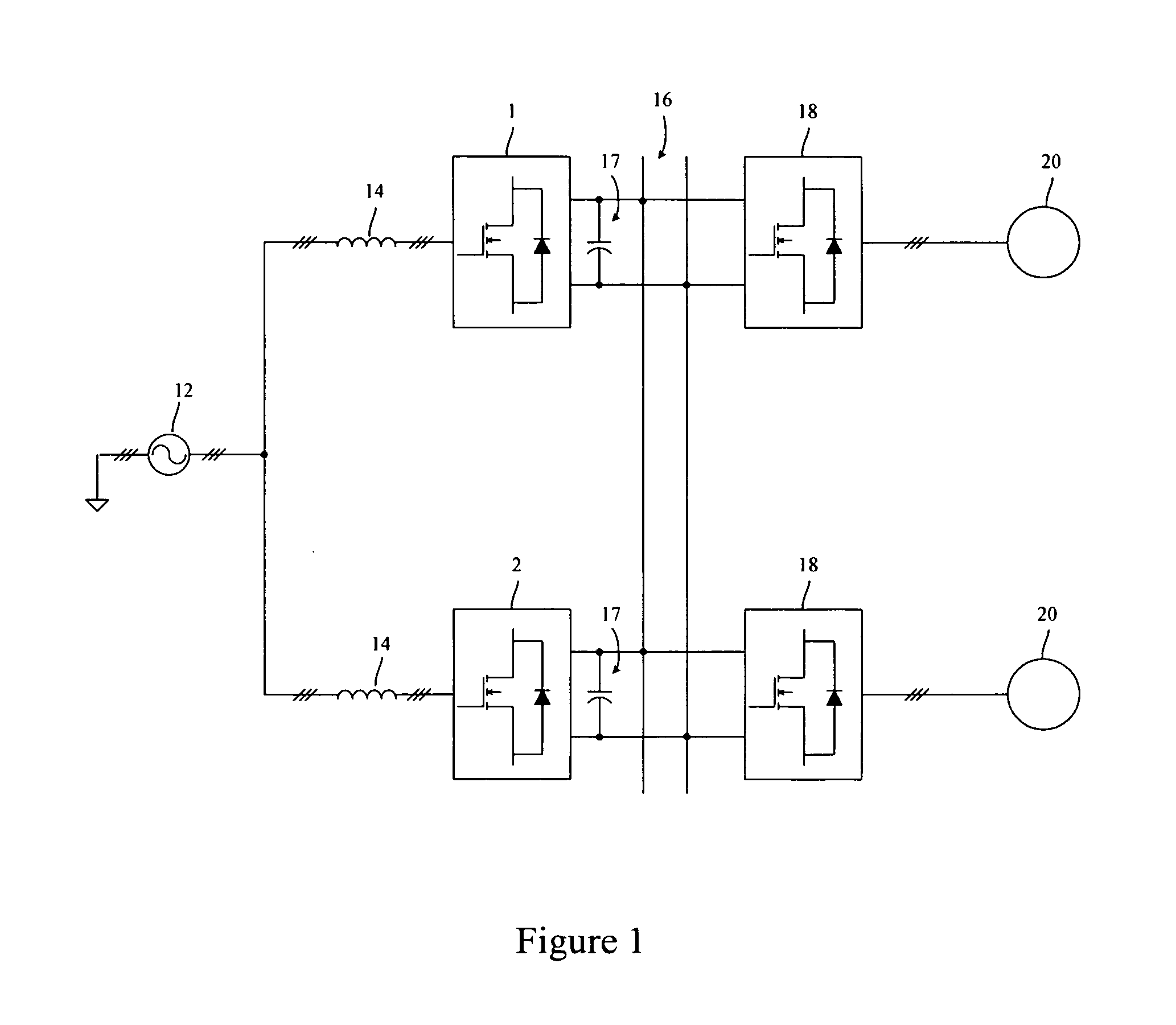
[0061]FIG. 1 is a schematic illustration showing a plurality of power converters 1, 2 connected in parallel. In the illustrated arrangement, the power converters 1, 2 operate as active rectifiers and have ac terminals connected to a common three phase ac source 12 via line reactors 14 and dc terminals connected to a common dc link 16, via dc link capacitors 17, to which power is supplied. Although two power converters 1, 2 are illustrated in FIG. 1, it should be understood that any suitable number of power converters may be provided and that this may depend, amongst other things, on the total power requirement.

[0062]Each power converter 1, 2 has a conventional three-phase two-level topology with a series of semiconductor power switching devices fully controlled and regulated using a pulse width modulation (PWM) switching strategy. However, in practi...


PUM


Abstract

A method is described for controlling a plurality of power converters 1, 2 connected in parallel between an ac arrangement 12 and a common dc link 16, each of the power converters 1, 2 operating in accordance with a pulse width modulation (PWM) strategy and having an independently variable dc link reference voltage. The method comprises modifying an output voltage droop characteristic of at least one of the plurality of parallel-connected power converters 1, 2 by varying the dc link reference voltage of the at least one power converter 1, 2 based on the output current of the at least one power converter 1, 2 and the average of the output currents of the plurality of power converters 1, 2.

Description

FIELD OF THE INVENTION[0001]The present invention relates generally to methods for controlling a plurality of parallel-connected power converters. More particularly, the present invention relates to methods for controlling a plurality of power converters connected in parallel between an ac arrangement and a common dc link. Embodiments of the present invention relate to methods for controlling a plurality of parallel-connected power converters operating with a pulse width modulation (PWM) strategy and which can be used to interface a motor requiring variable voltage at variable frequency to a three-phase supply network (ac busbar) at nominally fixed voltage and frequency. The methods can also be used for controlling a plurality of parallel-connected power converters operating with a PWM strategy that are used to interface generators providing variable voltage at variable frequency to a power grid or to a supply network at nominally fixed voltage and frequency.BACKGROUND ART[0002]As m...

Claims


Application Information

Patent Timeline
IPC IPC(8): H02M7/08
CPCH02M7/23
Inventor FENG, CHUNMEIMORENO-CASTANEDA, VEIMAR YOBANYWEBB, RICHARD STUARTKNIGHT, JEREMY STEPHEN PREVOST
Owner GE ENERGY POWER CONVERSION TECH
Learn More