Audio processing device, system, use and method

a processing device and audio technology, applied in the field of audio processing, can solve the problems of re-calibration of parts of the processing system, such as level estimators, and achieve the effects of reducing the number of channels being processed, reducing the bandwidth of individual channels, and reducing the number of channels

Active Publication Date: 2012-09-27
OTICON
View PDF2 Cites 27 Cited by
  • Summary
  • Abstract
  • Description
  • Claims
  • Application Information

AI Technical Summary

Benefits of technology

[0016]Sometimes, the bandwidth of the input signal is smaller than the bandwidth supported by a listening device, e.g. a hearing aid. This is e.g. the case when the input signal is a telephone signal, or other sound signals reproduced from devices with a reduced bandwidth. If such an input signal is detected, it can be advantageous to change the channel coupling so that the number of available (processing) channels only covers the bandwidth of the input signal. Hereby the frequency resolution of some of the channels becomes narrower (finer / better). This is e.g. shown in FIG. 5. Alternatively, the bandwidth of the individual channels can be maintained but the number of channels being processed can be reduced (whereby power can be conserved).

Problems solved by technology

A disadvantage of an instantaneous change of channel coupling may be that some parts of the processing system (such as level estimators) need re-calibration.

Method used


Image

  • Audio processing device, system, use and method
  • Audio processing device, system, use and method
  • Audio processing device, system, use and method

Examples


Embodiment Construction

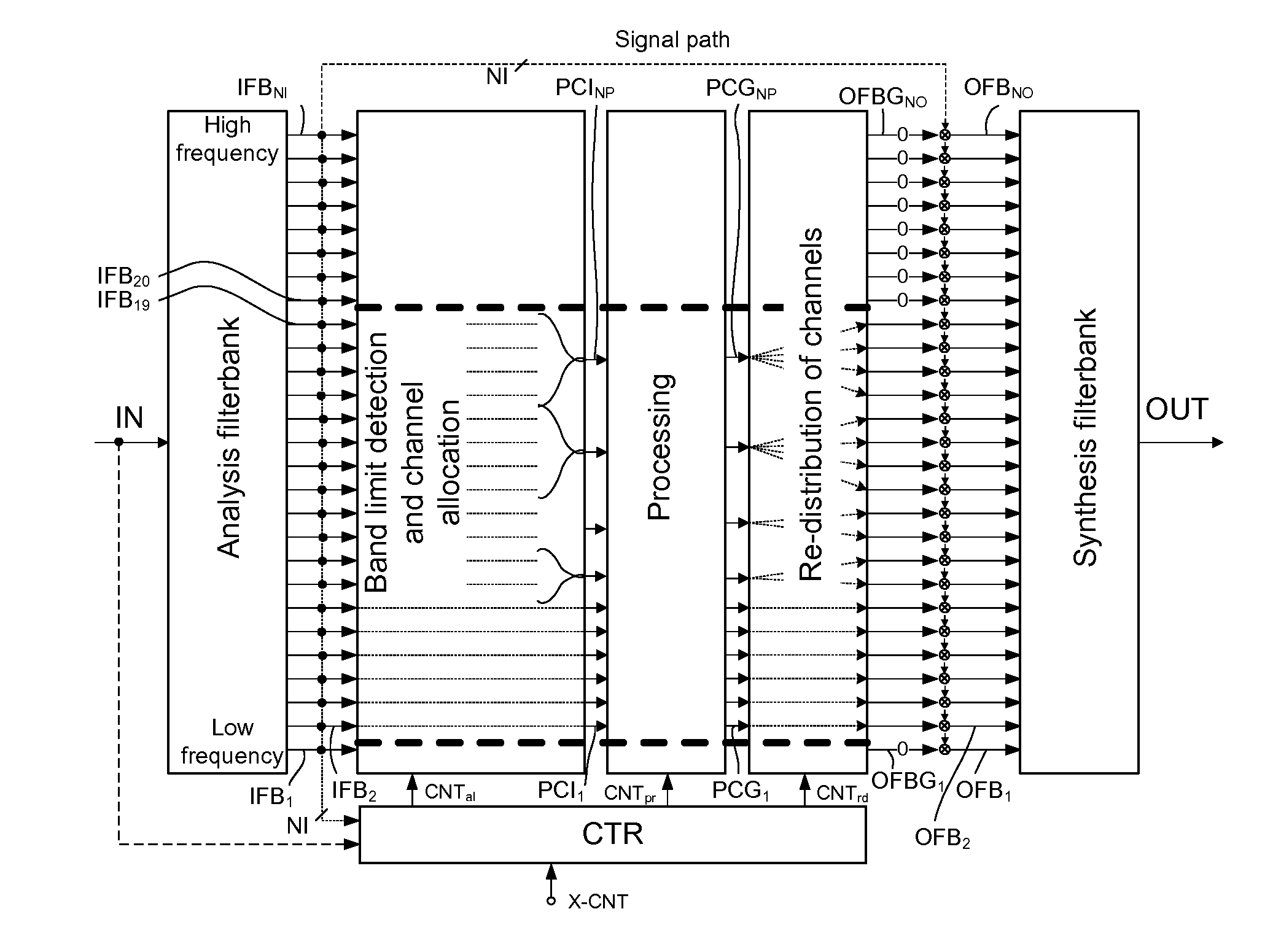
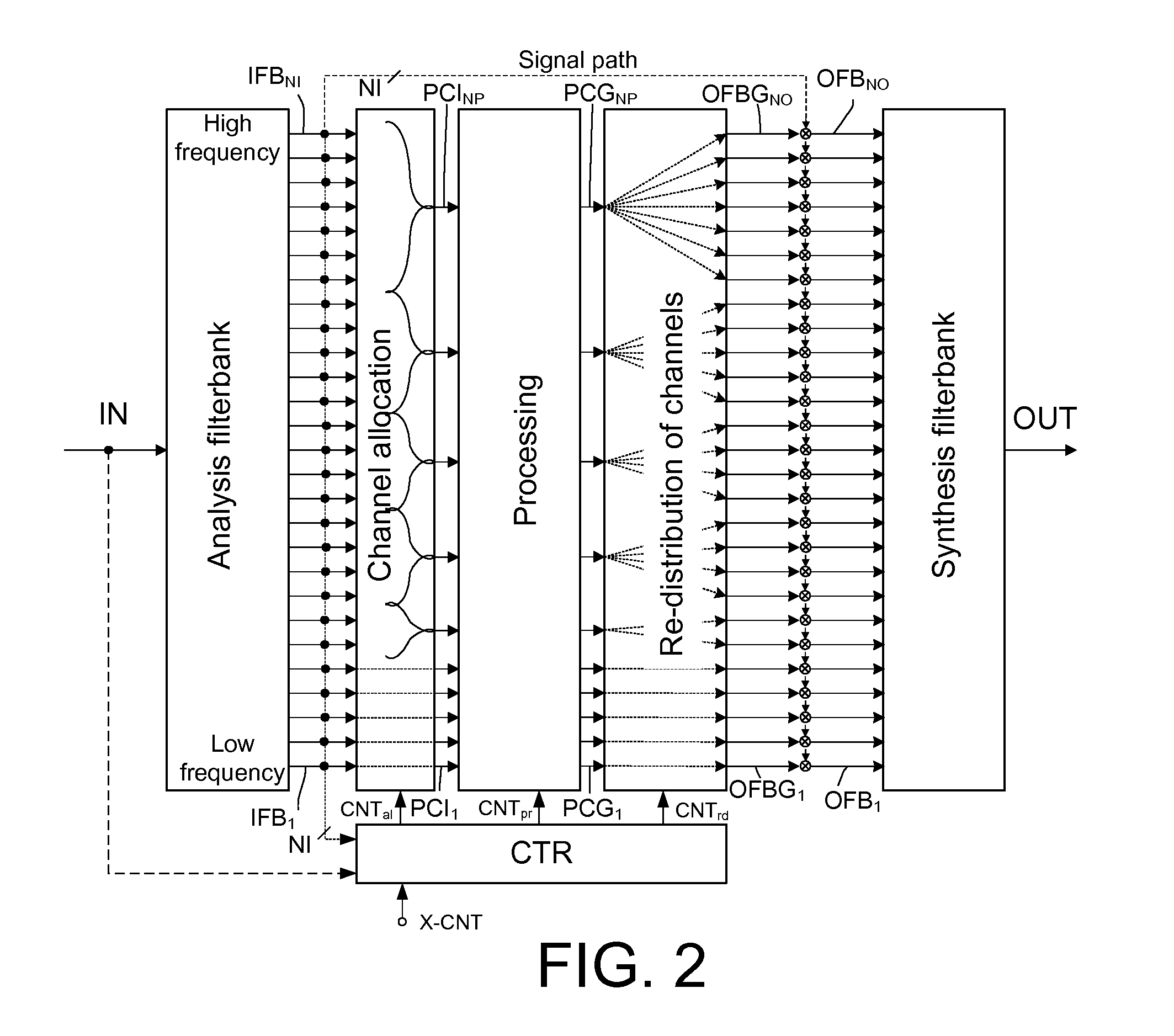
[0099]In the following the terms ‘frequency band’ and frequency band signal'(associating a frequency band with its contents) are used interchangeably.

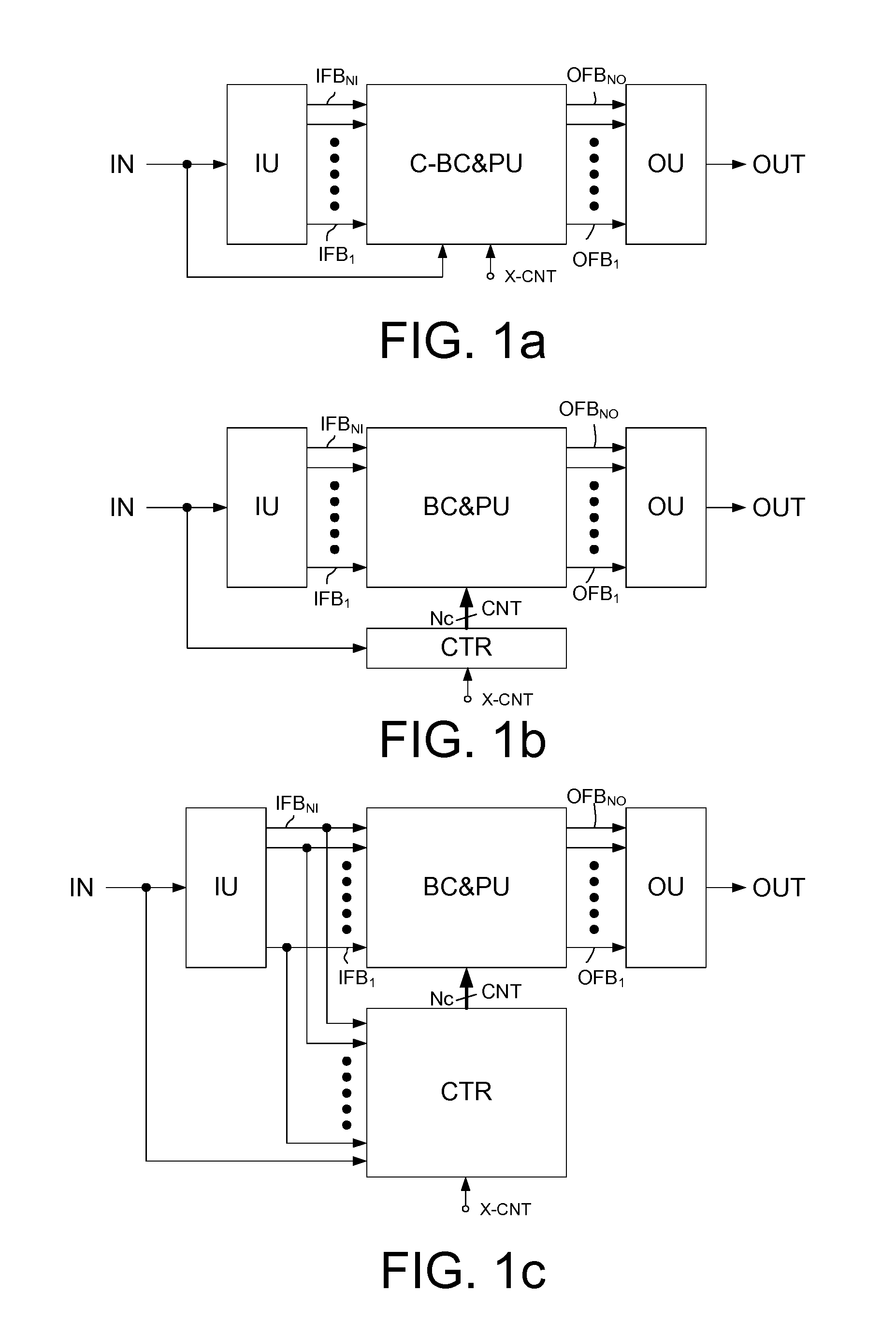
[0100]FIG. 1 shows three different embodiments of an audio processing device according to the present disclosure. All three embodiments comprise an input unit IU receiving a time domain electric input signal IN and an output unit OU for generating a time domain output signal OUT. The input unit IU is adapted to split or convert the time domain electric input signal IN to NI (time varying) signals IFB1, IFB2, . . . , IFBNI, each representing a frequency or frequency range, here referred to as NI input frequency bands. The input unit IU may e.g. be implemented as an (possibly uniform) analysis filter bank, e.g. by means of a

[0101]Fourier transformation unit (e.g. an FFT-unit or any other domain transform unit). The output unit OU is adapted for generating a time domain output signal OUT from a number NO of (time varying) signals OFB1, OF...


PUM


Abstract

An audio processing device includes a) an input unit for converting a time domain input signal to a number NI of input frequency bands and b) an output unit for converting a number NO of output frequency bands to a time domain output signal. A signal processing unit processes the input signal in a number NP of processing channels, smaller than the number NI of input frequency bands. A frequency band allocation unit allocates input frequency bands to processing channels. A frequency band redistribution unit redistributes processing channels to output frequency bands, and a control unit dynamically controls the allocation of input frequency bands to processing channels and the redistribution of processing channels to output frequency bands.

Description

CROSS REFERENCE TO RELATED APPLICATIONS[0001]This nonprovisional application claims the benefit under 35 USC §119(e) of U.S. Provisional Application No. 61 / 466,961 filed on Mar. 24, 2011 and under 35 USC §119(a) to European Patent Application No. 11159555.9 filed in the European Patent Office, on Mar. 24, 2011, all of which are hereby expressly incorporated by reference into the present application.TECHNICAL FIELD[0002]The present application relates to audio processing, in particular to optimizing audio processing to characteristics of a particular input audio signal and / or to a particular user's hearing ability. The disclosure relates specifically to an audio processing device for processing a number NI of input frequency bands and to a system comprising a number of audio processing devices (e.g. two). The application furthermore relates to the use of an audio processing device and to a method of processing an input audio signal.[0003]The application further relates to a data proc...

Claims


Application Information

Patent Timeline
Patent Type & Authority Applications(United States)
IPC IPC(8): H04R25/00H03G5/00
CPCH04R25/505H04R2225/41H04R2460/03H04R2430/03H04R2225/81H04R3/12H04R2430/00
Inventor PEDERSEN, MICHAEL SYSKIND
Owner OTICON
Why Eureka
Try Eureka