
Method for patterning a full metal gate structure

a metal gate structure and patterning technology, applied in the direction of basic electric elements, electrical equipment, semiconductor devices, etc., can solve the problems of poor profile control during pattern transfer, the integration of high-k materials with metal gate structures,

Inactive Publication Date: 2012-09-27
TOKYO ELECTRON LTD
View PDF16 Cites 11 Cited by
  • Summary
  • Abstract
  • Description
  • Claims
  • Application Information

AI Technical Summary

Benefits of technology

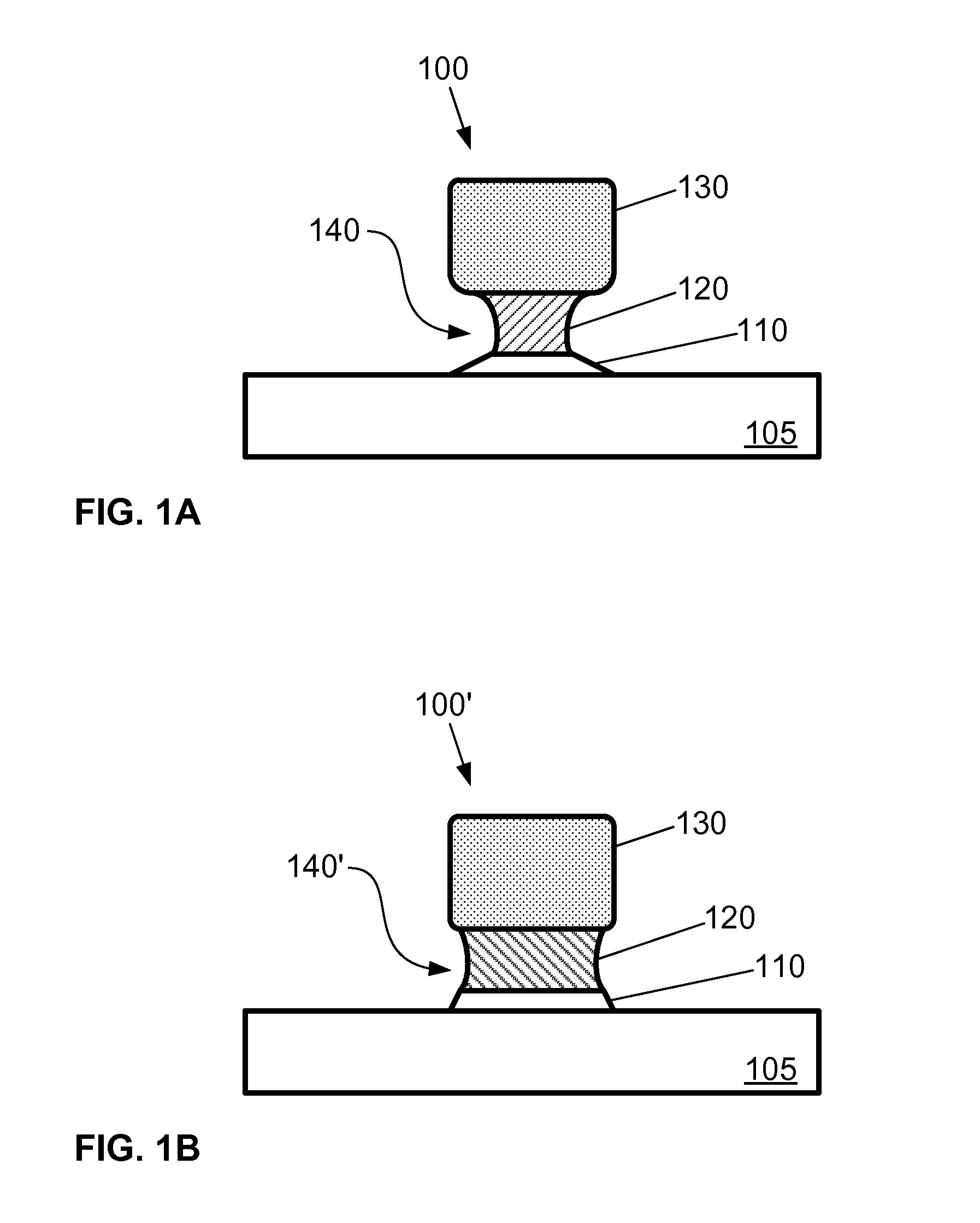
[0007]The invention relates to a method for etching a metal gate structure on a substrate using a plasma etching process and, in particular, a method for etching a metal gate structure to achieve profile control with reduced under-cutting.
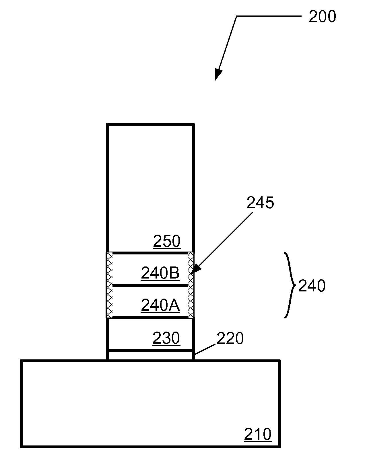
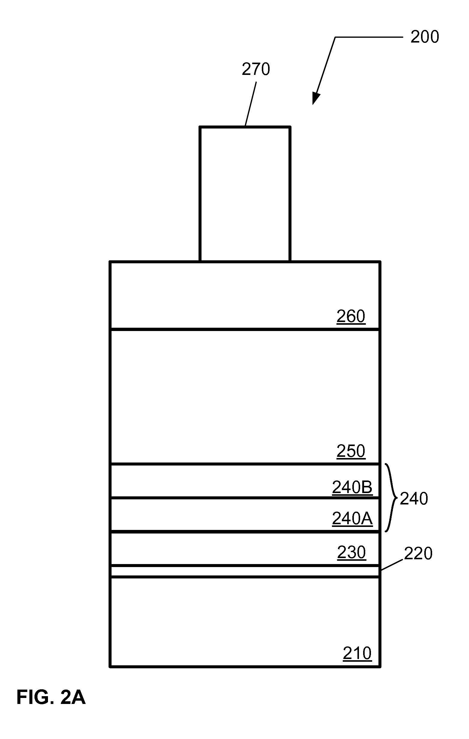
[0008]According to one embodiment, a method of patterning a gate structure on a substrate on a substrate is described. The method includes preparing a metal gate structure on a substrate, wherein the metal gate structure includes a high dielectric constant (high-k) layer, a first gate layer formed on the high-k layer, and a second gate layer formed on the first gate layer, and wherein the first gate layer comprises one or more metal-containing layers. The method further includes preparing a mask layer with a pattern overlying the metal gate structure, transferring the pattern to the second gate layer, transferring the pattern to the first gate layer, and transferring the pattern in the first gate layer to the high-k layer, and prior to the transferring of the pattern to the high-k layer, passivating an exposed surface of the first gate layer using a nitrogen-containing and / or carbon-containing environment to reduce under-cutting of the first gate layer relative to the second gate layer, wherein the passivating is performed separately from or in addition to the transferring of the pattern to the first gate layer.
[0009]According to another embodiment, a method of patterning a gate structure on a substrate, comprising: preparing a metal gate structure on a substrate, the metal gate structure including a high-k layer, a metal alloy layer formed on the high-k layer, and a gate layer formed on the metal alloy layer, the metal alloy layer comprising an Al-alloy and / or Ti-alloy; preparing a mask layer with a pattern overlying the metal gate structure; transferring the pattern to the gate layer; transferring the pattern to the metal alloy layer; transferring the pattern in the metal alloy layer to the high-k layer; and passivating an exposed surface of the metal alloy layer using a nitrogen-containing environment and / or carbon-containing environment to reduce under-cutting of the metal alloy layer relative to the gate layer.

Problems solved by technology

As the size of semiconductor devices is reduced, process development and integration issues are key challenges for new gate materials including high-permittivity (or high dielectric constant) dielectric materials (also referred to herein as high-k materials).
However, the integration of high-k materials with metal gate structures has posed substantive challenges during the patterning of the metal gate structure.
In particular, conventional etching processes suffer from poor profile control during pattern transfer.

Method used


Image

  • Method for patterning a full metal gate structure
  • Method for patterning a full metal gate structure
  • Method for patterning a full metal gate structure

Examples


Embodiment Construction

[0021]In the following description, for purposes of explanation and not limitation, specific details are set forth, such as a particular geometry of a processing system, descriptions of various components and processes used therein. However, it should be understood that the invention may be practiced in other embodiments that depart from these specific details.

[0022]Similarly, for purposes of explanation, specific numbers, materials, and configurations are set forth in order to provide a thorough understanding of the invention. Nevertheless, the invention may be practiced without specific details. Furthermore, it is understood that the various embodiments shown in the figures are illustrative representations and are not necessarily drawn to scale.

[0023]Various operations will be described as multiple discrete operations in turn, in a manner that is most helpful in understanding the invention. However, the order of description should not be construed as to imply that these operations...


PUM


Abstract

A method of patterning a gate structure on a substrate is described. The method includes preparing a metal gate structure on a substrate, wherein the metal gate structure includes a high dielectric constant (high-k) layer, a first gate layer formed on the high-k layer, and a second gate layer formed on the first gate layer, and wherein the first gate layer comprises one or more metal-containing layers. The method further includes preparing a mask layer with a pattern overlying the metal gate structure, transferring the pattern to the second gate layer, transferring the pattern to the first gate layer, and transferring the pattern in the first gate layer to the high-k layer, and prior to the transferring of the pattern to the high-k layer, passivating an exposed surface of the first gate layer using a nitrogen-containing and / or carbon-containing environment to reduce under-cutting of the first gate layer relative to the second gate layer, wherein the passivating is performed separately from or in addition to the transferring of the pattern to the first gate layer.

Description

BACKGROUND OF THE INVENTION[0001]1. Field of Invention[0002]The invention relates to a method for etching a metal gate structure on a substrate using a plasma etching process.[0003]2. Description of Related Art[0004]As the size of semiconductor devices is reduced, process development and integration issues are key challenges for new gate materials including high-permittivity (or high dielectric constant) dielectric materials (also referred to herein as high-k materials).[0005]Dielectric materials featuring a dielectric constant greater than that of SiO2 (k˜3.9) are commonly referred to as high-k materials. In addition, high-k materials may refer to dielectric materials that are deposited onto substrates (e.g., HfO2, ZrO2) rather than grown on the surface of the substrate (e.g., SiO2, SiNxOy). High-k materials may incorporate metallic silicates or oxides (e.g., Ta2O5 (k˜26), TiO2 (k˜80), ZrO2 (k˜25), Al2O3 (k˜9), HfSiO, HfO2 (k˜25)).[0006]For front-end-of-line (FEOL) operations, thes...

Claims


Application Information

Patent Timeline
Patent Type & Authority Applications(United States)
IPC IPC(8): H01L21/28
CPCH01L21/28247H01L21/31122H01L21/32136H01L21/28123H01L29/517H01L29/518H01L21/32138H01L21/28H01L21/311H01L21/3213
Inventor LUONG, VINH HOANGKO, AKITERU
Owner TOKYO ELECTRON LTD
Learn More