[0007]It is one purpose of the present invention to provide an air conditioning / dehumidifying unit which unit is much easier and cheaper to build, install, operate, and service than known units. It is also the purpose of the present invention to provide a unit which is more versatile and efficient in operation than known units. It is another purpose of the present invention to provide an air conditioning / dehumidifying unit for indoor swimming pools which can be easily modified to simply and effectively heat
pool water when required. It is a further purpose to the present invention to provide methods of simply and easily conditioning and treating air in enclosed spaces, and particularly in indoor swimming pools, and for heating
swimming pool water when needed.
[0008]In accordance with the present invention there is provided an air conditioning / dehumidifying unit having novel air passageway means allowing use of a single condenser rather than two condensers. The unit is compact and thus requires a much smaller charge of refrigerant resulting in significant
cost savings and, even more likely, in the use of alternative, more costly, environmental-friendly refrigerants. The unit is substantially completely assembled and tested at the place of manufacture and not at the installation site. No separate installation of a second condenser at the site is required. No mounting pad for a second condenser is needed and no installation of refrigerant lines or a separate electrical service is needed at the site. The unit is fully charged with refrigerant at the factory and not at the site thereby minimizing the possibility of refrigerant
contamination or compressor damage while charging in the field. The unit can be fully tested at the factory rather than waiting for some of the testing to be completed at the site. The unit, being compact, is easily shipped and installed. Shipping costs are reduced since there is no separate, second condenser to ship.
[0009]The air conditioning / dehumidifying unit of the present invention can be readily operated in an air-conditioning mode, a dehumidifying mode; and a purge / ventilating mode. The unit, when used in an indoor swimming pool, can be modified to have a pool
water heater and can be further operated in a pool
water heating mode; an air-conditioning / pool
water heating mode; and a dehumidifying / pool water heating mode. The unit can simply and easily modulate the head pressure of the refrigerant during operation thereby providing better efficiencies in the operation; better control of the properties of the air within the indoor area and better control of the heating of the pool water if a pool
water heater is employed. The unit can also provide for lower static pressure during operation resulting in reduced operating costs.
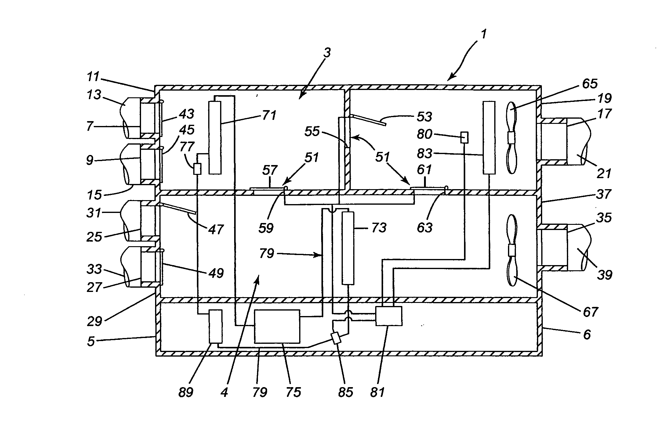
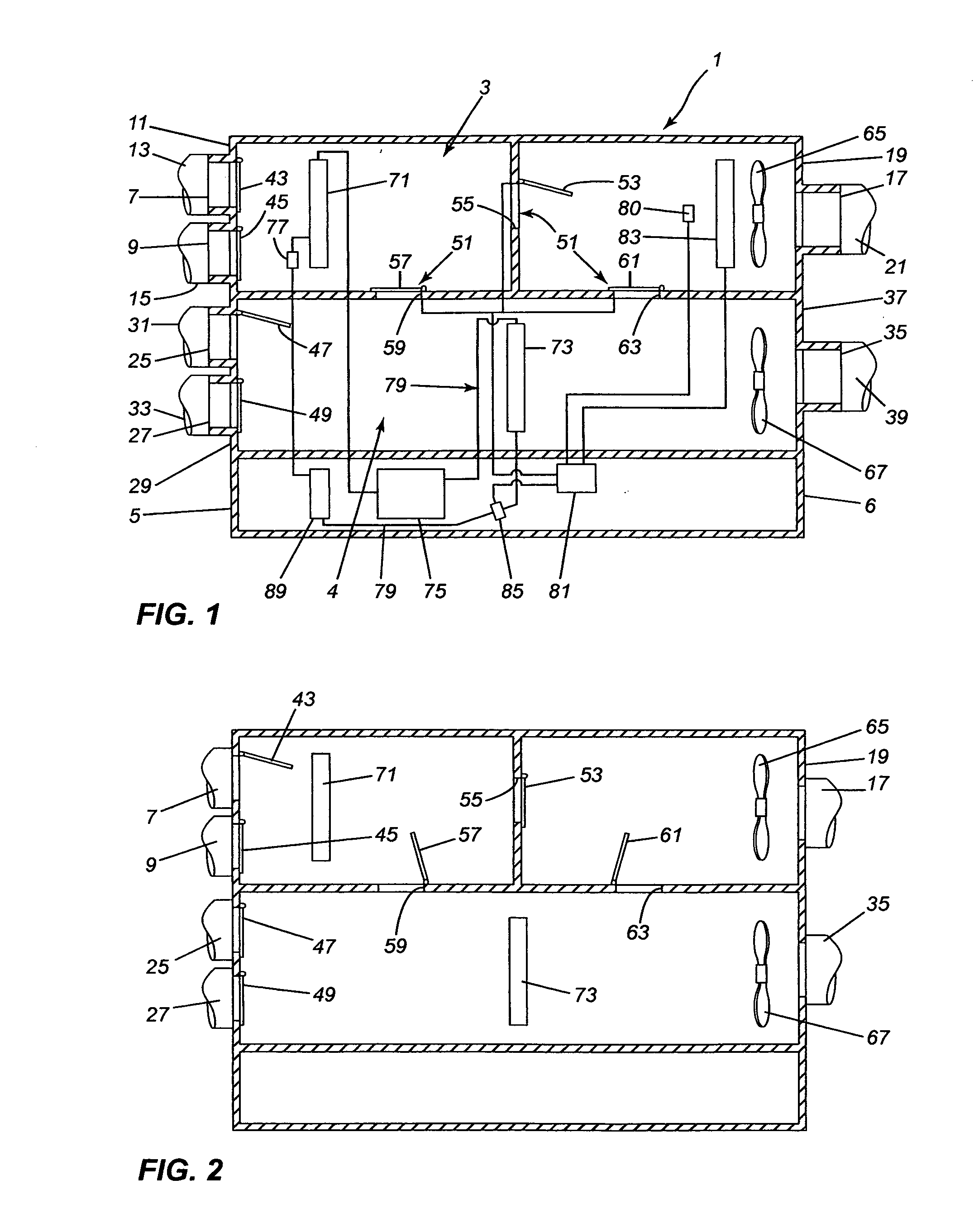
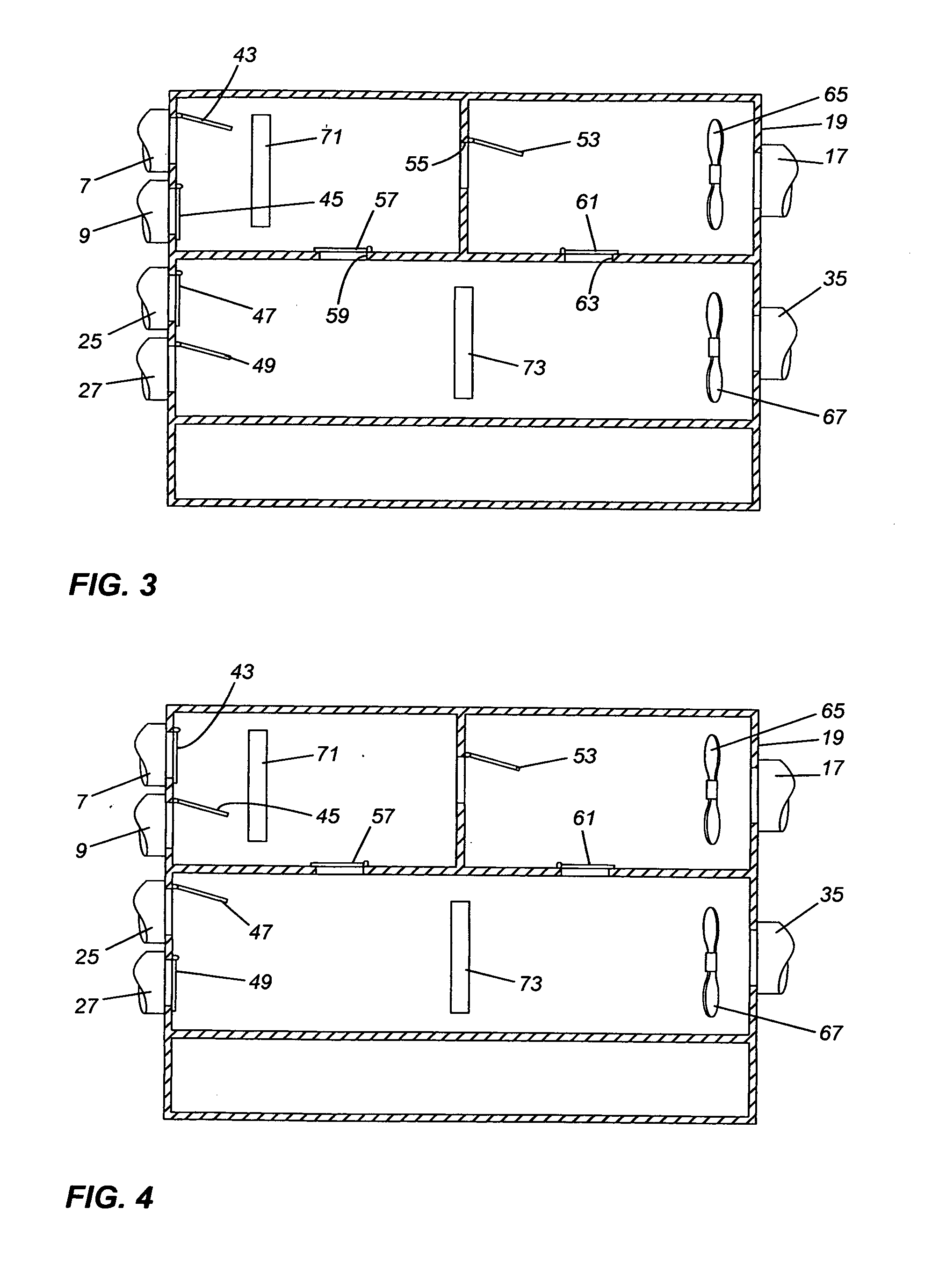
[0016]The construction of the unit, in having the evaporator in a first passageway and the condenser in a second adjacent passageway, separate from the first passageway, provides for more efficient operation of the unit. The second passageway can be substantially larger in cross-sectional area than the first passageway and thus the face area of the condenser can be increased compared to the face area of the evaporator to increase the efficiency of the unit. During dehumidifying, the air passing through the condenser can have a larger area to pass through, reducing static pressure and thus reducing the power required to move the air. During air conditioning, the outside air passing through the second passageway and the condenser is at a lower static pressure since the air does not pass through the evaporator, which can be clogged with water droplets, and since the size of the condenser is increased. In addition, the static pressure in the first passageway is lowered when at least some of the air passes out through the passageway from the evaporator to the indoor area without having to pass through the condenser during dehumidifying and when all of the air from the evaporator avoids the condenser during air conditioning. As a result of reducing static pressure, overall
power consumption is reduced.
[0017]The air conditioning / dehumidifying unit, when used in an indoor swimming pool, can have a pool water
heat exchanger for heating pool water. With a pool water heat exchanger, the unit can be used to heat pool water, to dehumidify and heat pool water simultaneously, or to air condition and heat pool water simultaneously.
Refrigerant from the condenser is passed directly through the heat exchanger to heat the water. The heating of the pool water is fully modulated by controlling the flow of water through the pool water heat exchanger. If the temperature of the water drops below a
set point, the flow of pool water is started through the heat exchanger, via a pump in the water
system, by opening a water valve. The flow can be increased by further opening of the valve if required. The temperature of the refrigerant passing through the heat exchanger is controlled by controlling its head pressure. The head pressure is controlled by modulating the flow of air over the condenser through the
damper assembly. If the air flow is reduced, the head pressure is increased, increasing the temperature of the refrigerant. If the air flow is increased, the head pressure is reduced, reducing the temperature of the refrigerant.
Refrigerant normally enters the pool water heat exchanger as a hot gas to heat the water and as a hot or warm liquid when little or no heating is required. If there is no pool water flowing through the heat exchanger, the head pressure is decreased to have refrigerant flow as a warm liquid through the heat exchanger so as to avoid overheating the stagnant water in the heat exchanger.
[0018]The unit provides simple control of the head pressure of the refrigerant without requiring the use of expensive regulating valves. During most
modes of operation of the unit, the temperature of the refrigerant, either after leaving the condenser, or after leaving the pool water heat exchanger, can be sensed by a temperature sensor to give an indication of the head pressure. If the temperature sensed is low, the temperature sensor can control the
damper assembly or the outside
air blower to allow less air flow through the condenser thus increasing the head pressure. If the temperature sensed is high, the
damper assembly, during dehumidifying, dehumidifying / pool water heating or pool water heating
modes, can be modulated to allow more air to flow through the condenser thus lowering the head pressure. During air conditioning and air conditioning / pool water heating
modes, the outside
air blower speed can be modulated to control the flow of outside air through the condenser to control head pressure.

