Loop heat pipe structure

a technology of heat pipe and loop, which is applied in the direction of lighting and heating apparatus, basic electric elements, and semiconductor devices, etc., can solve the problems of correspondingly increasing waste heat, serious heat leakage, and relatively high local thermal resistance, and achieves improved overall heat dissipation efficiency, reduced pressure loss, and high saturation vapor pressure

Active Publication Date: 2012-10-04
ASIA VITAL COMPONENTSSHEN ZHEN
View PDF15 Cites 13 Cited by
  • Summary
  • Abstract
  • Description
  • Claims
  • Application Information

AI Technical Summary

Benefits of technology

[0009]The above-described first wick layer provides sufficient capillary force required by the whole loop heat pipe structure to work normally, and reduces the pressure loss caused by the movement of the working fluid through the first wick layer. The above-described second wick layer serves as a heat lock layer to effectively prevent the heat transferred to the first wick layer from entering into the second chamber to cause heat leak. That is, the working fluid will not be overheated to form vapor-liquid phase equilibrium and produce high saturation vapor pressure in the second chamber, allowing the liquid-phase working fluid in the transport pipe to return to the second chamber. Therefore, the loop heat pipe structure of the present invention can avoid the occurrence of very high vapor pressure in the evaporator and enable upgraded overall heat dissipation efficiency.

Problems solved by technology

While the IC chips have significantly increased computing speed and functions, they also generate correspondingly increased waste heat.
While the conventional loop heat pipe structure provides a lot of advantages, it has a cylindrical evaporator that occupies a relatively large space and fails to directly contact with the heat source due to the round outer surface thereof.
With only one type of wick structure provided in the evaporator, heat that heats the evaporator can also easily enter into the reservoir or compensation chamber to cause serious heat leak.
In the event a single layer of wick structure with low thermal conductivity is used to prevent the heat leak, another problem of relatively high local thermal resistance would occur in the evaporator.
On the other hand, when a single layer of wick structure with high thermal conductivity is used, it would become very difficult to initialize the flat plate loop heat pipe structure.
In other words, the flat plate loop heat pipe structure having one single layer of wick structure with high thermal conductivity requires an extremely high critical power for the initialization thereof and even could not be started up in some special working condition.
A combined effect of the above two conditions badly affects the thermal performance of the flat plate loop heat pipe structure to even offset the advantages thereof.

Method used


Image

  • Loop heat pipe structure
  • Loop heat pipe structure
  • Loop heat pipe structure

Examples


Embodiment Construction

[0021]The present invention will now be described with some preferred embodiments thereof and with reference to the accompanying drawings. For the purpose of easy to understand, elements that are the same in the preferred embodiments are denoted by the same reference numerals.

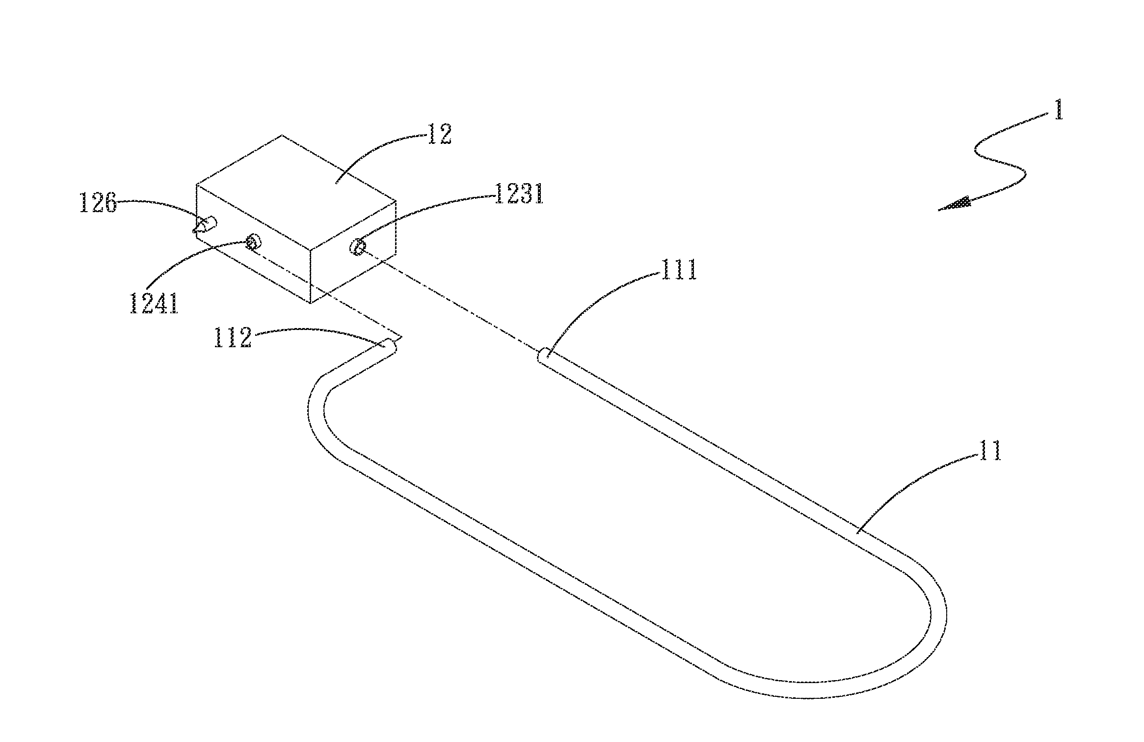
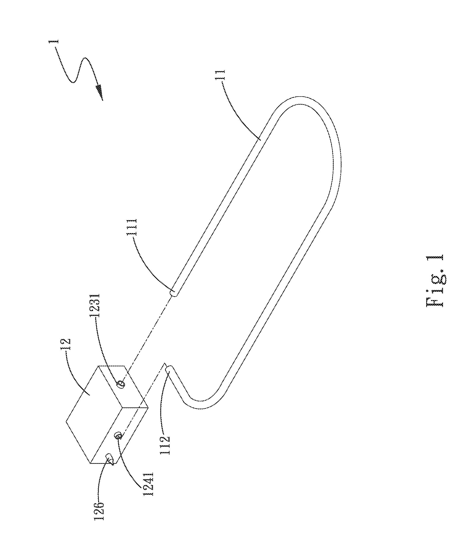
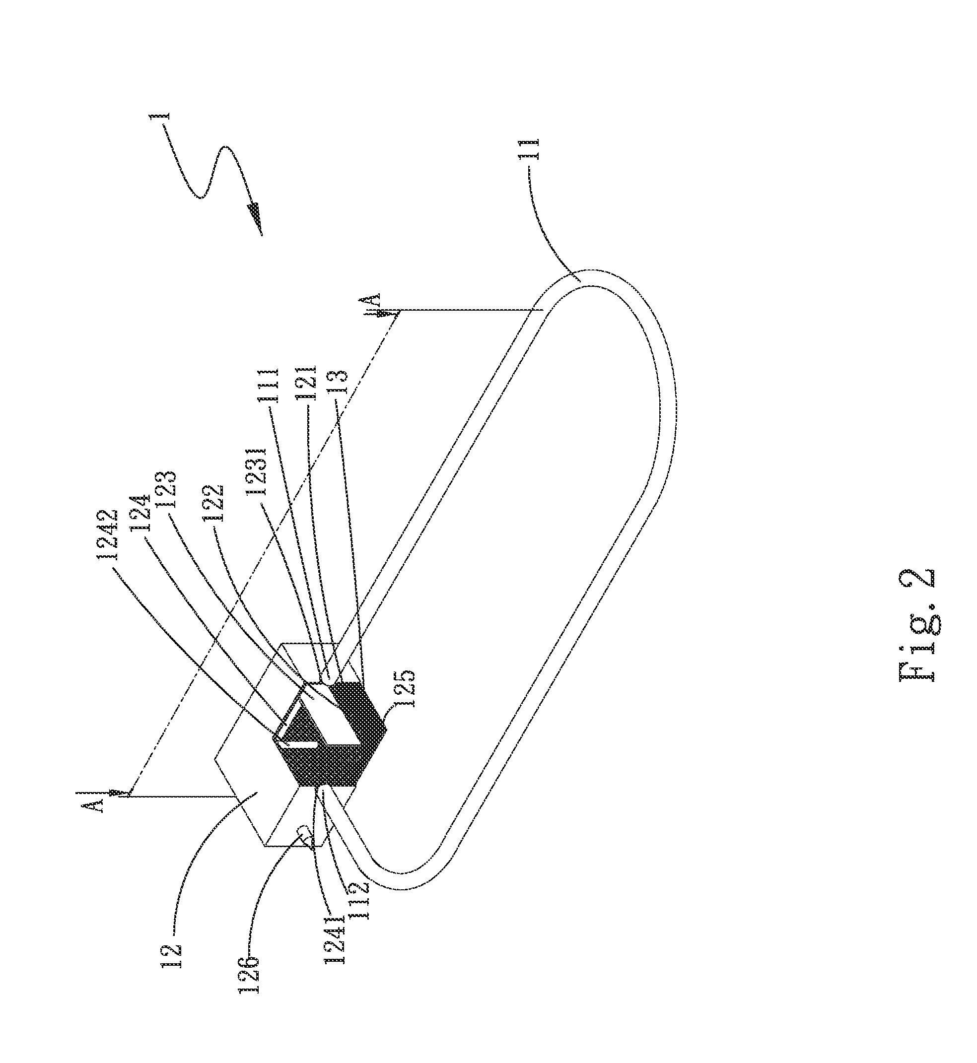
[0022]Please refer to FIGS. 1 and 2 that are exploded perspective and cutaway views, respectively, of a loop heat pipe structure 1 according to a first embodiment of the present invention, and to FIG. 3 that is a sectional view taken along line A-A of FIG. 2. As shown, the loop heat pipe structure 1 in the first embodiment includes a transport pipe 11, an evaporator 12, a first wick layer 121, a second wick layer 122, and a plurality of grooves 13.

[0023]The transport pipe 11 has a first end 111 and a second end 112, and internally defines a flow passage 113 communicating with the first and the second end 111, 112.

[0024]The evaporator 12 has a bottom 125, internally defines a first chamber 123 and a second chamb...


PUM


Abstract

A loop heat pipe structure includes a transport pipe, an evaporator, a first wick layer, a second wick layer, and a plurality of grooves. The transport pipe communicates with the evaporator. The evaporator has a bottom and internally defines a first chamber and a second chamber, and has a working fluid filled therein. The first wick layer is located on the bottom, and the second wick layer is located on and covers the first wick layer. The grooves can be selectively provided on the first wick layer or the bottom. The first and second wick layers are so designed that the situation of very high vapor pressure would not occur in the second chamber, enabling the loop heat pipe structure to have upgraded heat dissipation efficiency.

Description

[0001]This application claims the priority benefit of China patent application number 201110076381.8 filed on Mar. 29, 2011.FIELD OF THE INVENTION[0002]The present invention relates to a loop heat pipe structure, and more particularly to a loop heat pipe structure that includes an evaporator internally provided with superposed wick layers having different thermal conductivity and permeability to thereby avoid very high vapor pressure in the evaporator and enable upgraded overall heat dissipation efficiency.BACKGROUND OF THE INVENTION[0003]Due to the progress in the semiconductor technology, integrated circuit (IC) chips have been widely used in various electronic apparatus, such as personal computers, notebook computers and network servers. While the IC chips have significantly increased computing speed and functions, they also generate correspondingly increased waste heat. Such waste heat must be effectively removed to protect the electronic apparatus against failure. Various heat ...

Claims


Application Information

Patent Timeline
Patent Type & Authority Applications(United States)
IPC IPC(8): F28D15/04
CPCH01L23/427H05K7/20336F28D15/0266F28D15/0275H01L2924/0002F28D15/046H01L2924/00
Inventor XIANG, JUNZHOU, XIAO-XIANGCHIANG, KUEI-FENG
Owner ASIA VITAL COMPONENTSSHEN ZHEN
Why Eureka
Try Eureka