
Signal generating device and frequency synthesizer

a signal generation and frequency synthesizer technology, applied in the direction of generating/distributing signals, pulse automatic control, instruments, etc., can solve the problems of insufficient technique to reduce phase noise, insufficient simplified circuit, and limit in improving spurious characteristics, so as to achieve low noise and improve spurious characteristics

Active Publication Date: 2012-10-04
NIHON DEMPA KOGYO CO LTD
View PDF2 Cites 6 Cited by
  • Summary
  • Abstract
  • Description
  • Claims
  • Application Information

AI Technical Summary

Benefits of technology

[0028]The present invention focuses attention on the point that for generating the reference frequency signal used, for example, in the frequency synthesizer using a PLL based on the clock when detecting a previously set threshold value, for example, the zero cross point of the sawtooth wave composed of the digital signal, the digital value does not always become the threshold value since the digital values are skipped values. Therefore, two clock signals before and after the threshold value are used at a ratio corresponding to the ratio between the digital value immediately before and the digital value immediately after the digital value crosses over the threshold value in a region where the digital value gradually changes. Therefore, it is possible to obtain a frequency signal with lower noise than that in a method of using the clock signal immediately before or immediately after the threshold value in a single uniform manner. By configuring the frequency synthesizer using the frequency signal, an effect of improving spurious characteristics is achieved.

Problems solved by technology

However, such a device performs A / D (analog / digital) conversion and then processes and D / A converts the digital signal, and thus has a limit in improving the spurious characteristics.
In addition, there is a problem that its circuit is not sufficiently simplified because of both A / D conversion and D / A conversion.
However, when a reference signal is generated using the signal generator to form a PLL, the zero cross of the triangular wave cannot be accurately detected, and therefore the technique is not enough to decrease the phase noise.

Method used


Image

  • Signal generating device and frequency synthesizer
  • Signal generating device and frequency synthesizer
  • Signal generating device and frequency synthesizer

Examples


example

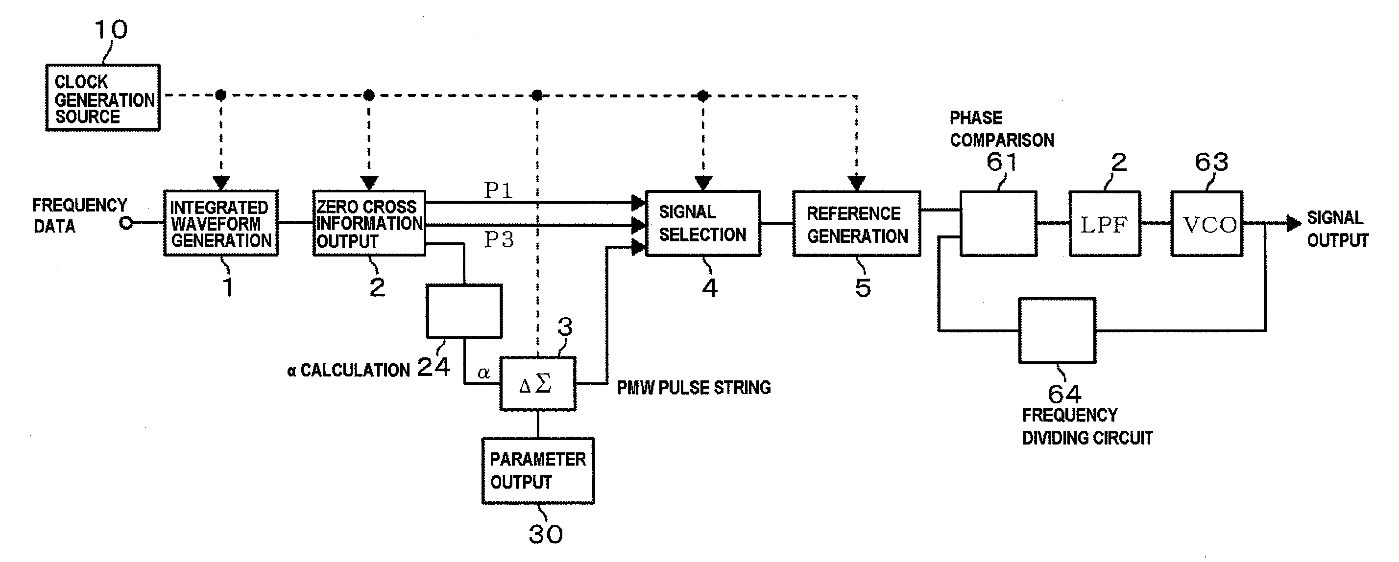
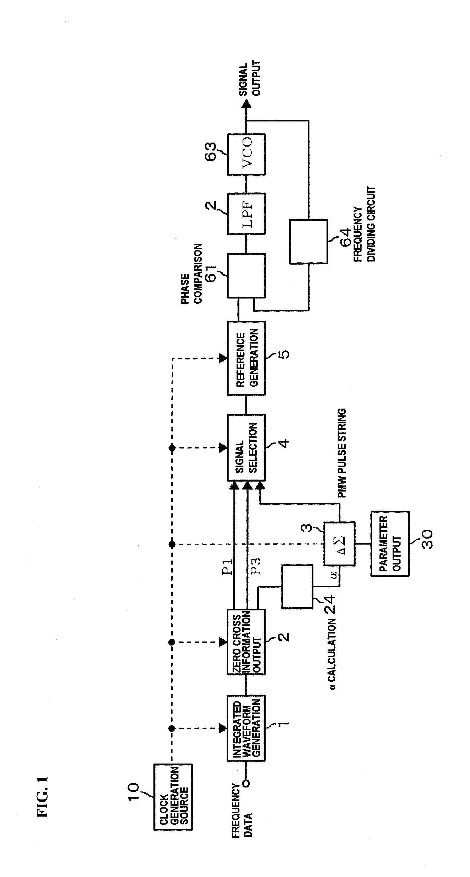
[0068]To confirm the effects of the present invention, the spurious characteristics of the frequency signal obtained from the reference signal generation unit 5 were investigated in the case of using the circuit illustrated in FIG. 1 (Example) and in the case of using only the clock signal P3 as the zero cross point (Comparative Example) respectively. The reference signal generation unit 5 is composed of a DDS (Direct Digital Synthesizer) and has a set frequency of 312.5 kHz. Note that the latter comparative example was carried out with the ΔΣ circuit 3 stopped in the circuit illustrated in FIG. 1. FIG. 12 is a graph indicating the spurious characteristics, in which A is for Example and B is for Comparative Example. As is found from the results, the spurious characteristics are excellent in the present invention.


PUM


Abstract

A frequency synthesizer using a PLL has a simple structure and excellent spurious characteristics. A reference frequency signal inputted into a phase comparison unit is generated based on a clock when a zero cross point of a sawtooth wave composed of a digital signal is detected. However, in this case, since the digital values are skipped values, the digital value does not always become zero when its positive / negative sign is inverted. Hence, where the clock signals reading the digital value immediately before and the to digital value immediately after the zero cross time when the positive / negative sign is inverted in a region where the digital value gradually changes are P1 and P2 respectively and the clock signal at a timing next to the clock signal P2 is P3, P1 and P3 are used at a ratio corresponding to the ratio between the digital values read by P1 and P2.

Description

BACKGROUND OF THE INVENTION[0001]1. Field of the Invention[0002]The present invention relates to a signal generating device and a frequency synthesizer.[0003]2. Description of the Related Art[0004]As one of standard signal generators, there is a known frequency synthesizer using a PLL (Phase Locked Loop) which is applied to, for example, a local oscillating part in a mobile station, a test signal source of a radio communication device, a broadcasting device, and the like. When the frequency synthesizer is applied in, for example, a communication field, its noise has to be small in order to avoid interference with other channels, and it is desirably capable of setting the frequency as finely as possible in the state that radio waves are congested.[0005]Hence this applicant has developed a frequency synthesizer with a simple circuit configuration satisfying the above needs, and its technique has already been disclosed in Patent Document 1 and the like. For example, in the method in Pa...

Claims


Application Information

Patent Timeline
Patent Type & Authority Applications(United States)
IPC IPC(8): H03L7/06G06F1/04
CPCH03L7/099G06F1/022H03L7/18
Inventor AKAIKE, KAZUOKOBATA, TSUKASA
Owner NIHON DEMPA KOGYO CO LTD
Learn More