Optical Buffering Methods, Apparatus, and Systems for Increasing the Repetition Rate of Tunable Light Sources

a buffering method and optical buffering technology, applied in the field of frequencytunable light sources, can solve the problems of limiting the available optical gain, affecting the effective duty cycle of continuously swept light sources, and affecting the effect of image quality degradation

Active Publication Date: 2012-10-04
LIGHTLAB IMAGING
View PDF7 Cites 132 Cited by
  • Summary
  • Abstract
  • Description
  • Claims
  • Application Information

AI Technical Summary

Benefits of technology

[0023]In one embodiment, the present invention enables acquisition of interferometric image data at high-repetition rates using optical buffering without degradation of image quality.

Problems solved by technology

One of the major impediments to higher speed operation of frequency-domain systems, especially systems that operate continuously over a wide spectral range, is the sweep repetition rate of the light source.
This occurs because the time required to build up stimulated emission limits the available optical gain within the filter bandpass.
Such unsdesirable broadening can occur during either the up sweep (the portion of the sweep over which the wavelength increases) or the down sweep (the portion of the sweep over which the wavelength decreases), such that a significant portion of the sweep becomes unusable.
These factors impose an upper limit on the effective duty cycle of continuously swept light sources.
These requirements increase system cost and complexity.
Additionally, the optical throughput of such conventional optical buffer configurations is relatively low.
In certain applications, an optical power loss of this magnitude can negatively impact a system's signal-to-noise ratio.

Method used


Image

  • Optical Buffering Methods, Apparatus, and Systems for Increasing the Repetition Rate of Tunable Light Sources
  • Optical Buffering Methods, Apparatus, and Systems for Increasing the Repetition Rate of Tunable Light Sources
  • Optical Buffering Methods, Apparatus, and Systems for Increasing the Repetition Rate of Tunable Light Sources

Examples


Embodiment Construction

[0040]The following description refers to the accompanying drawings that illustrate certain embodiments of the invention. Other embodiments are possible and modifications may be made to the embodiments without departing from the spirit and scope of the invention. Therefore, the following detailed description is not meant to limit the invention. Rather, the scope of the invention is defined by the appended claims.

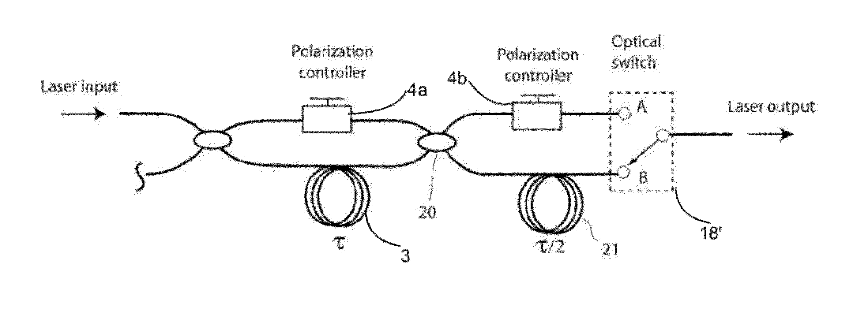
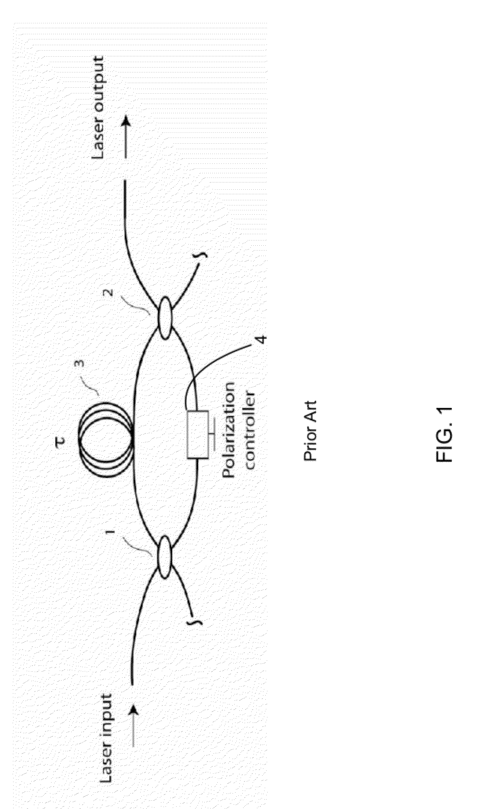
[0041]Embodiments of the invention describe improved methods, systems, and devices, such as optical buffers, interferometer switches, and other elements arranged according to specific configurations for use with various data collection and imaging modalities such as optical coherence tomography.

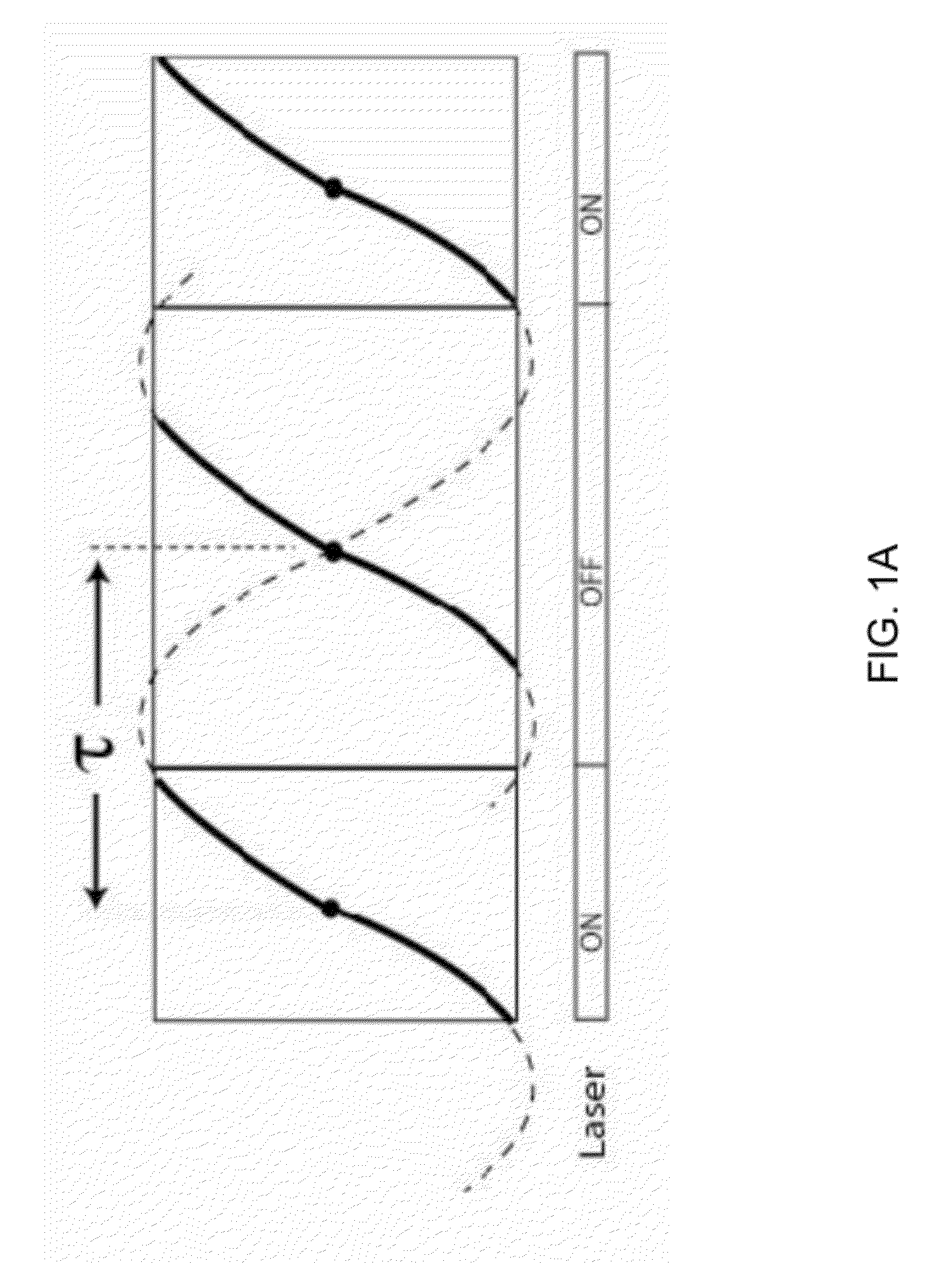
[0042]In general, the invention relates to methods and apparatuses for increasing the repetition rate or rate at which the tunable frequencies of a swept source can be swept. These methods and apparatuses increase the repetition rate of a tunable light source by replicating a certain ...


PUM

PropertyMeasurementUnit
insertion lossesaaaaaaaaaa
optical coherence tomographyaaaaaaaaaa
frequency-aaaaaaaaaa

Abstract

In one embodiment, the invention relates to an apparatus for increasing the repetition rate in a light source. The apparatus includes a first optical coupler comprising a first arm, a second arm and a third arm; a first mirror in optical communication with the second arm of the first optical coupler; and a first optical delay line having a first end in optical communication with the third arm of the first optical coupler and a second end in optical communication with a second mirror, wherein light entering the first arm of the first optical coupler leaves the first arm of the first optical coupler either delayed by an amount (τ) or substantially undelayed.

Description

FIELD OF INVENTION[0001]This invention relates generally to the field of frequency-tunable light sources and more specifically to their application in optical measurement and imaging systems.BACKGROUND[0002]New applications of measurement and imaging systems that employ tunable light sources demand increasingly higher data acquisition rates. For example, although the latest generation of frequency-domain optical coherence tomography (OCT) systems for imaging of coronary arteries acquire image data at 50,000 lines / sec, even faster speeds are necessary to scan the full lengths of the major coronary branches. Scanning spectrometers must also operate at higher speeds to permit rapid analysis of atmospheric aerosols and contaminants over large areas, hyperspectral imaging of moving targets, detection of chemical substances in multiple samples, and other applications.[0003]One of the major impediments to higher speed operation of frequency-domain systems, especially systems that operate c...

Claims


Application Information

Patent Timeline
Patent Type & Authority Applications(United States)
IPC IPC(8): G02B6/27F21V11/00G01B9/02G02B6/26G02B6/35
CPCG02B6/3502G02B6/2861G01B9/02004G01B9/02091G02B6/2808
Inventor SCHMITT, JOSEPH M.ADLER, DESMOND
Owner LIGHTLAB IMAGING
Why Eureka
Try Eureka