Transmitter and receiver synchronization for wireless telemetry systems

a wireless telemetry and transmitter technology, applied in the field of telemetry systems, can solve the problems of difficult to provide such communication using a cable, and additional complexity of the cable inside the tubing

Inactive Publication Date: 2012-10-04
SCHLUMBERGER TECH CORP
View PDF6 Cites 53 Cited by
  • Summary
  • Abstract
  • Description
  • Claims
  • Application Information

AI Technical Summary

Benefits of technology

[0028]In another aspect, the present disclosure describes a computer system having one or more input device, one or more output device, and one or more non-transitory computer readable medium storing instructions for (1) receiving a priori information of a particular, planned tubing for a borehole from the one or more input device, (2) predicting optimal carrier frequencies for acoustic communication utilizing the particular, planned tubing as a communication channel between two or more modems,

Problems solved by technology

One of the more difficult problems associated with any borehole is to communicate measured data between one or more locations down a borehole and the surface, or between downhole locations themselves.
Similarly when operating some of the downhole testing tools from surface, such as tester valves, circulating valves, packers, samplers or perforating charges, the operators do not obtain a direct feedback from the downhole tools.
However, it can be difficult to provide such communication using a cable since inside the tubing string it limits the flow diameter and requires complex structures to pass the cable from the inside to the outside of the tubing.
A cable inside the tubing is also an additional complexity in case of emergency disconnect for an offshore platform.
Space outside the tubing is limited and a cable can easily be damaged.
With respect to the non-uniform lengths, this is typically caused by the pipe sections being repaired by cutting part of the connection to re-machine the threads.
It will be appreciated that t

Method used


Image

  • Transmitter and receiver synchronization for wireless telemetry systems
  • Transmitter and receiver synchronization for wireless telemetry systems
  • Transmitter and receiver synchronization for wireless telemetry systems

Examples


Embodiment Construction

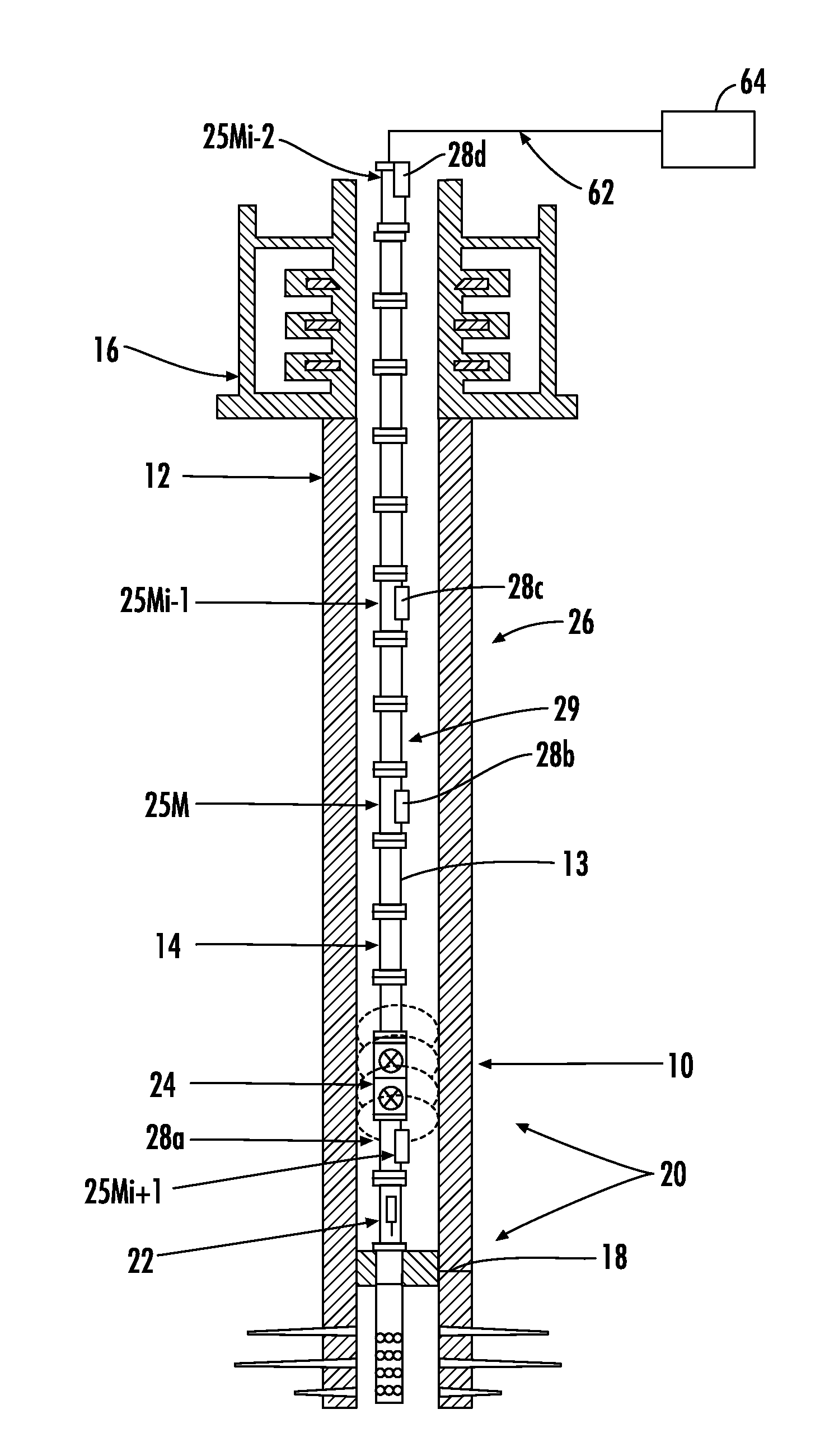
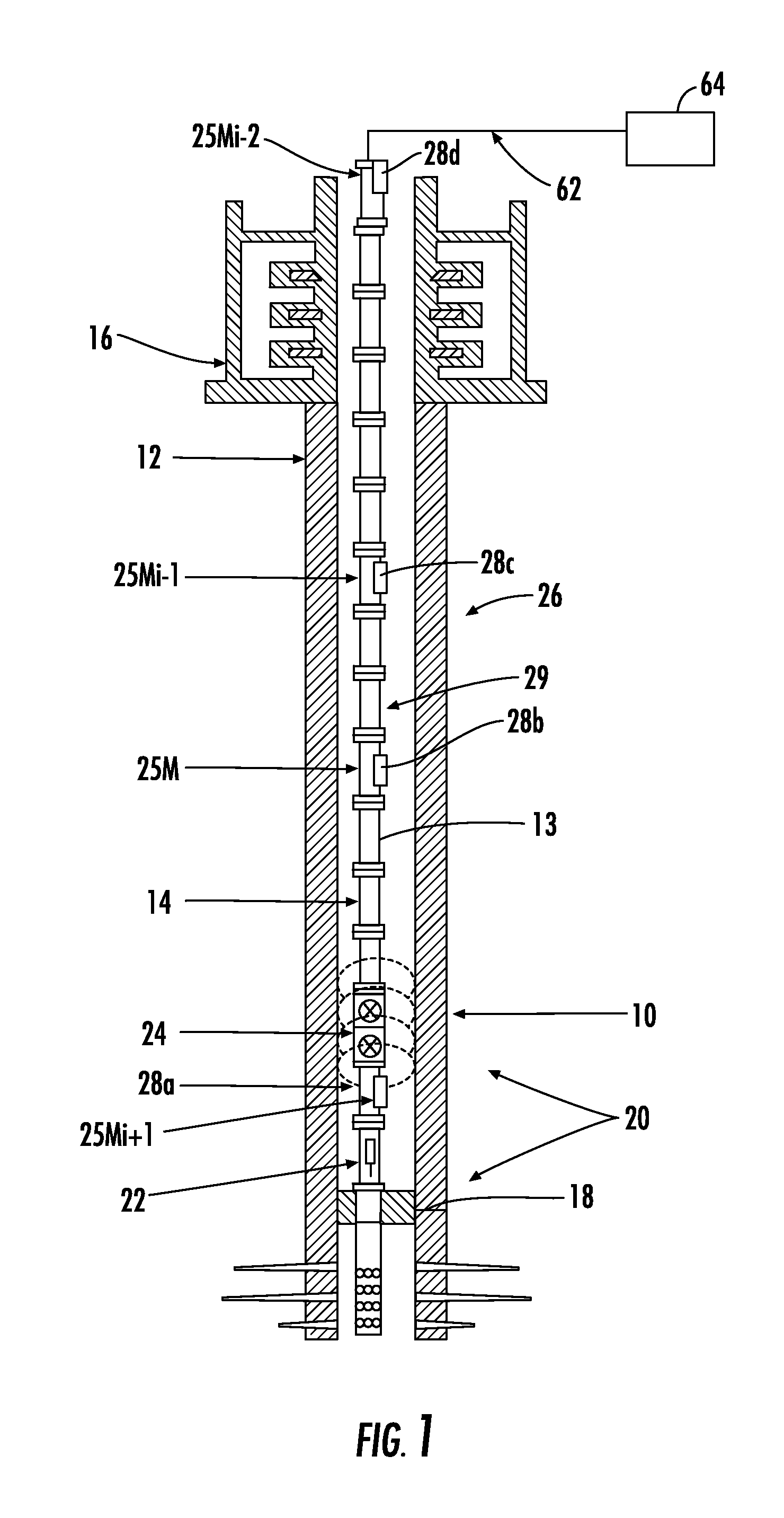
[0044]The present invention is particularly applicable to testing installations such as are used in oil and gas wells or the like. FIG. 1 shows a schematic view of such a system. Once a well 10 has been drilled through a formation, the drill string can be used to perform tests, and determine various properties of the formation through which the well has been drilled. In the example of FIG. 1, the well 10 has been lined with a steel casing 12 (cased hole) in the conventional manner, although similar systems can be used in unlined (open hole) environments. In order to test the formations, it is preferable to place testing apparatus in the well close to the regions to be tested, to be able to isolate sections or intervals of the well, and to convey fluids from the regions of interest to the surface. This is commonly done using a jointed tubular drill pipe, drill string, production tubing, sections thereof, or the like (collectively, tubing 14) which extends from well-head equipment 16 ...


PUM


Abstract

An acoustic modem for communication in a network of acoustic modems via a communication channel. The acoustic modem comprises a transceiver assembly, transceiver electronics, and a power supply. The transceiver assembly is adapted to convert acoustic messages into electrical signals. The transceiver electronics is provided with transmitter electronics and receiver electronics. The transmitter electronics cause the transceiver assembly to send acoustic signals into the communication channel. The receiver electronics comprises at least one microcontroller adapted to execute instructions to (1) enable the receiver electronics to receive electrical signals indicative of the acoustic message from at least one other acoustic modem via the transceiver assembly, (2) estimate a carrier frequency of the electrical signals by analyzing an estimation frame of the electrical signals, (3) estimate a starting time of a data frame of the electrical signals by synchronizing with a synchronization frame of the acoustic message in parallel with at least two bit rates, and (4) decode the data frame. The power supply supplies power to the transceiver assembly and the transceiver electronics.

Description

CROSS-REFERENCE TO RELATED APPLICATIONS[0001]Not applicable.TECHNICAL FIELD[0002]The present invention relates to telemetry systems for use with installations in oil and gas wells or the like. In particular, the present invention relates to the transmission of data and control signals between a location down a borehole and the surface, or between downhole locations themselves.BACKGROUND ART[0003]One of the more difficult problems associated with any borehole is to communicate measured data between one or more locations down a borehole and the surface, or between downhole locations themselves. For example, in the oil and gas industry it is desirable to communicate data generated downhole to the surface during operations such as drilling, perforating, fracturing, and drill stem or well testing; and during production operations such as reservoir evaluation testing, pressure and temperature monitoring. Communication is also desired to transmit intelligence from the surface to downhole t...

Claims


Application Information

Patent Timeline
IPC IPC(8): E21B47/14
CPCH04B11/00E21B47/16
Inventor MILLOT, GUILLAUMEFROELICH, BENOIT
Owner SCHLUMBERGER TECH CORP
Why Eureka
Try Eureka