Power control apparatus and power control method of construction machine

a technology of power control apparatus and construction machine, which is applied in the direction of machines/engines, positive displacement liquid engines, servomotors, etc., can solve the problems of reduced hydraulic pump flow rate, increased exhaust fumes, and severe vibrations, so as to improve fuel efficiency and reduce vibrations , the effect of preventing the rpm of the engin

Active Publication Date: 2012-10-04
DOOSAN INFRACORE CO LTD
View PDF12 Cites 18 Cited by
  • Summary
  • Abstract
  • Description
  • Claims
  • Application Information

AI Technical Summary

Benefits of technology

[0017]The present disclosure has been made in an effort to solve the above-mentioned problem, and it is an object of the present disclosure to provide a power control apparatus of a construction machine which can constantly maintain an RPM of an engine at a target RPM, thereby enhancing fuel efficiency.
[0037]In addition, by setting the present time a horse power difference value ΔPO between a current pump requiring horse power of the hydraulic pump and the target pump requiring horse power, horse power can be promptly controlled when the horse power difference value ΔPO is small, and a control time sufficient enough not to generate a hydraulic impact can be secured when the horse power difference value ΔPO is large.

Problems solved by technology

However, a flow rate of the hydraulic pump is reduced by the constant horse power regulating part after a predetermined time from a time point where a discharge pressure of the hydraulic pump due to a response delay time of the constant horse power regulating part.
If an engine RPM is abruptly lowered in this way, exhaust fumes increase and vibrations become severe as well.
In particular, in a section (turbo charger time lack section) where a drive of a turbocharger reaches a normal state as in section B of FIG. 1, an output increase rate of the engine becomes lower, further lowering the above-mentioned engine RPM and further deteriorating exhaust fumes and vibrations.
In summary of the problems of the above-mentioned power control apparatus according to the related art, a hydraulic impact by which a required horse power of the hydraulic pump is abruptly increased is generated due to a time delay of a constant horse power control point by the constant horse power regulating part.
Accordingly, an RPM of the engine abruptly decreases, causing severe exhaust fumes and vibrations.
Accordingly, even when the load transferred from the hydraulic pump to the engine is low, the engine maintains a high RPM, causing much energy loss.

Method used


Image

  • Power control apparatus and power control method of construction machine
  • Power control apparatus and power control method of construction machine
  • Power control apparatus and power control method of construction machine

Examples


Embodiment Construction

[0064]Hereinafter, a power control apparatus of a construction machine according to an exemplary embodiment of the present disclosure will be described in detail with reference to the accompanying drawings.

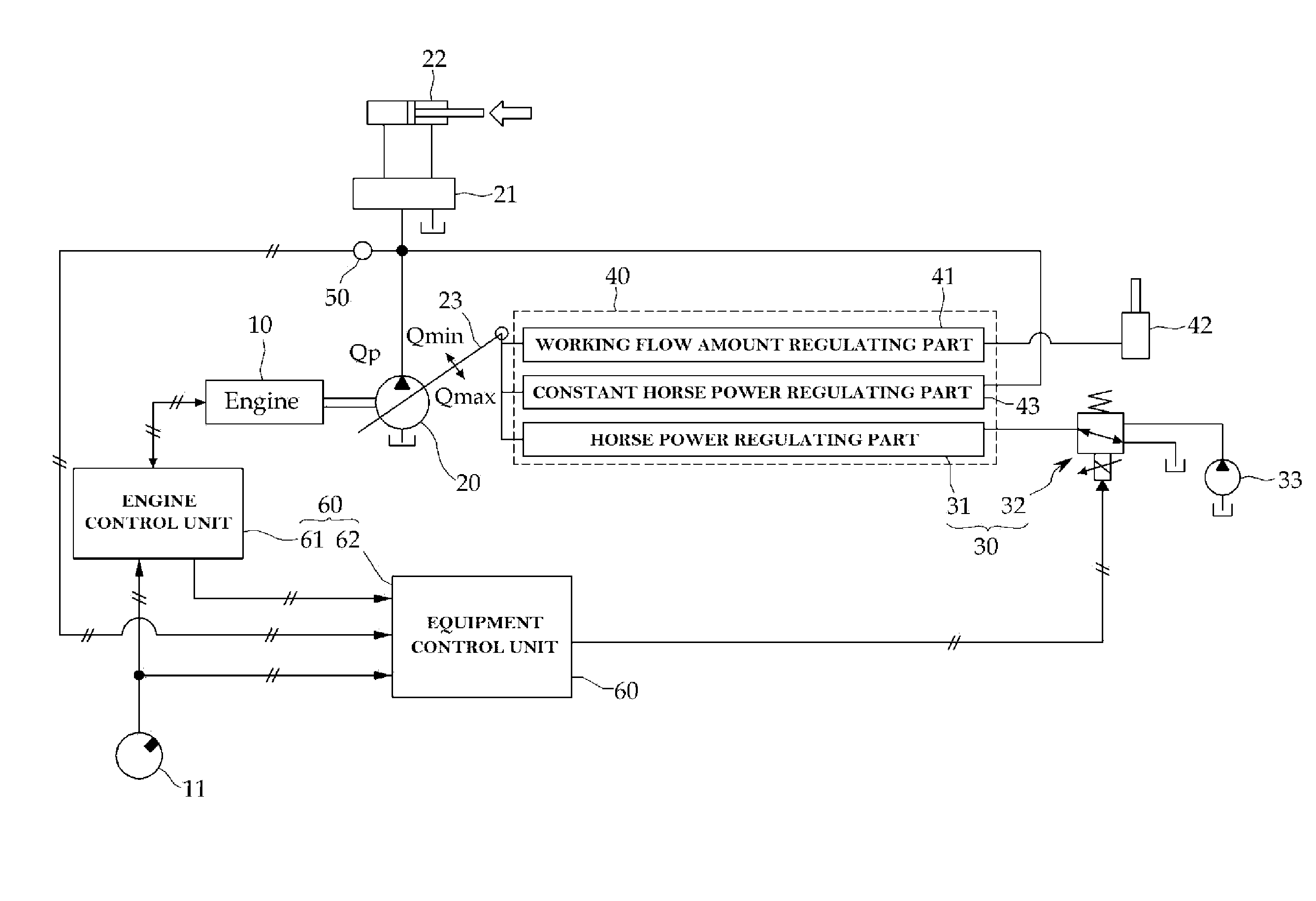
[0065]Referring to FIG. 4, the power control apparatus of a construction machine according to the exemplary embodiment of the present disclosure includes an engine 10 driving a hydraulic pump 20, a horst power regulating unit 30 for varying a swash plate angle of the hydraulic pump 20 to vary a required horse power of the hydraulic pump 20 in response to an input horse power control signal, a pressure sensor 50 for detecting a pressure of a working fluid discharged from the hydraulic pump 20, and a controller 60 for outputting the horse power control signal to the horse power regulating unit 30 and controlling an RPM of an engine as well.

[0066]The controller 60 includes an engine control unit 61 such as an electronic control unit (ECU) and an equipment control unit 62.

[0067]The en...


PUM


Abstract

The present disclosure provides a power control apparatus of a construction machine, including: an engine connected to a hydraulic pump to drive the hydraulic pump; and a controller for calculating an engine load ratio defined as a ratio of a load torque of the engine for an engine maximum torque calculated from an input engine target RPM, and calculating an engine RPM command value according to the engine load ratio such that the engine is driven at the target RPM to output the calculated engine load ratio and engine RPM command value to the engine.

Description

[0001]This Application is a Section 371 National Stage Application of International Application No. PCT / KR2010 / 009207, filed Dec. 22, 2010 and published, not in English, as WO2011 / 078578 on Jun. 30, 2011.FIELD OF THE DISCLOSURE[0002]The present disclosure relates to a power control apparatus of a construction machine such as a excavator, and more particularly, to a power control apparatus of a construction machine which controls an RPM of an engine according to a load ratio of the engine such that the engine can be constantly driven at a target RPM, thereby enhancing fuel efficiency.[0003]Also, the present disclosures relates to a power control apparatus and a power control method of a construction machine such as an excavator, and more particularly, to a power control apparatus and a power control method of a construction machine which can gradually increase a pump requiring horse power according to a load pressure of a hydraulic pump, thereby preventing a hydraulic impact.BACKGROU...

Claims


Application Information

Patent Timeline
Patent Type & Authority Applications(United States)
IPC IPC(8): E02F9/22F15B11/028F02D29/04
CPCE02F9/2066E02F9/2235E02F9/2246E02F9/2296F15B2211/633F15B2211/20523F15B2211/26F15B2211/6309F02D29/04
Inventor SOHN, WON SUNPARK, DUCK WOOBANG, JAE SEOK
Owner DOOSAN INFRACORE CO LTD
Why Eureka
Try Eureka