Fluoropolymer Barrier Materials for Containers

a technology of fluoropolymer and barrier material, which is applied in the direction of rigid pipes, bottling operations, synthetic resin layered products, etc., can solve the problems of syringe construction, leachable and extractable contaminants in the elastomer of the stopper, and the apparent challenges of conventional syringe technology

Active Publication Date: 2012-10-04
WL GORE & ASSOC INC
View PDF4 Cites 77 Cited by
  • Summary
  • Abstract
  • Description
  • Claims
  • Application Information

AI Technical Summary

Problems solved by technology

As more pharmaceuticals and particularly biopharmaceuticals utilize delivery in pre-filled syringe and similar devices, the challenges of conventional syringe technology become apparent.
Several aspects of traditional syringe construction present a challenge for their use as pre-filled syringes.
The use of silicone oil is a concern, because the oil may degrade the medicament and because a small amount of silicone may be injected with it.
Another issue that arises in prefilled syringes is that the elastomer of the stopper may contain leachable and extractable contaminants.
These may also contaminate the medicament upon long term storage in syringes.
Trace amounts of residual monomer or plasticizer or other impurities from the stopper can adversely effect the therapeutic or can have an adverse impact on the patient once injected.

Method used


Image

  • Fluoropolymer Barrier Materials for Containers
  • Fluoropolymer Barrier Materials for Containers
  • Fluoropolymer Barrier Materials for Containers

Examples


example 1a , 1b and 1c

Example 1A, 1B and 1C

[0079]Examples of certain embodiments of the invention were constructed using a single layer of densified ePTFE films as the barrier. The films were obtained by process described in U.S. Pat. No. 7,521,010 to Kennedy, et al. The films had thicknesses of 25 microns, 10 microns, and 5 microns, respectively. Eight commonly available disposable plastic syringe barrels and stoppers with shafts were obtained. Four were 1 ml plastic syringes and four were 3 ml plastic syringes. Each included an elastomer stopper comprising a butyl rubber. The syringes were thoroughly washed with 95% hexane to remove any silicone oil. The washed syringe barrels and stoppers were allowed to dry for 5 days on an airhood to ensure complete evaporation of the hexane. Syringe stoppers were made by taking a densified ePTFE film and applying it to the stopper. Samples were made using these different film thicknesses. The films were first heated by a heat gun (Karl Leister, CH 6056—Hotwind S) s...

example 2

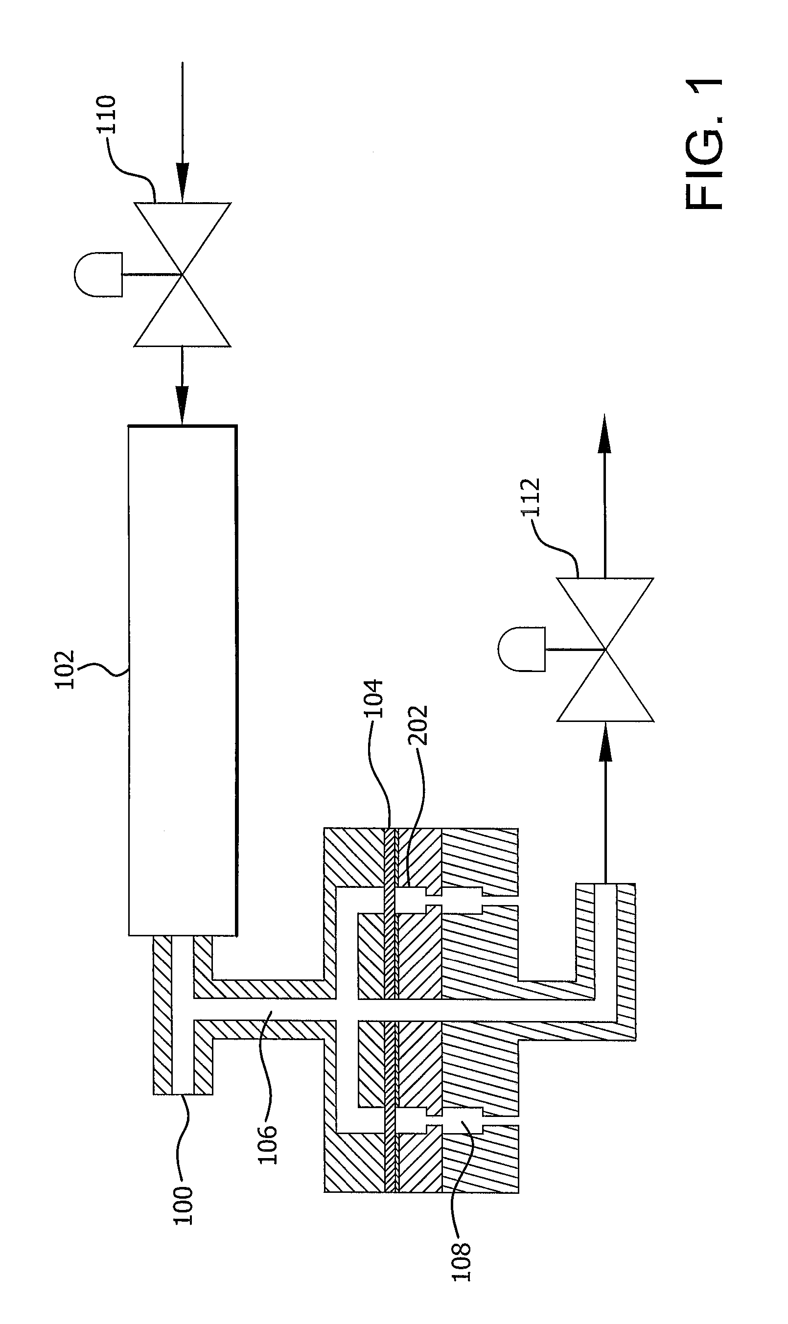
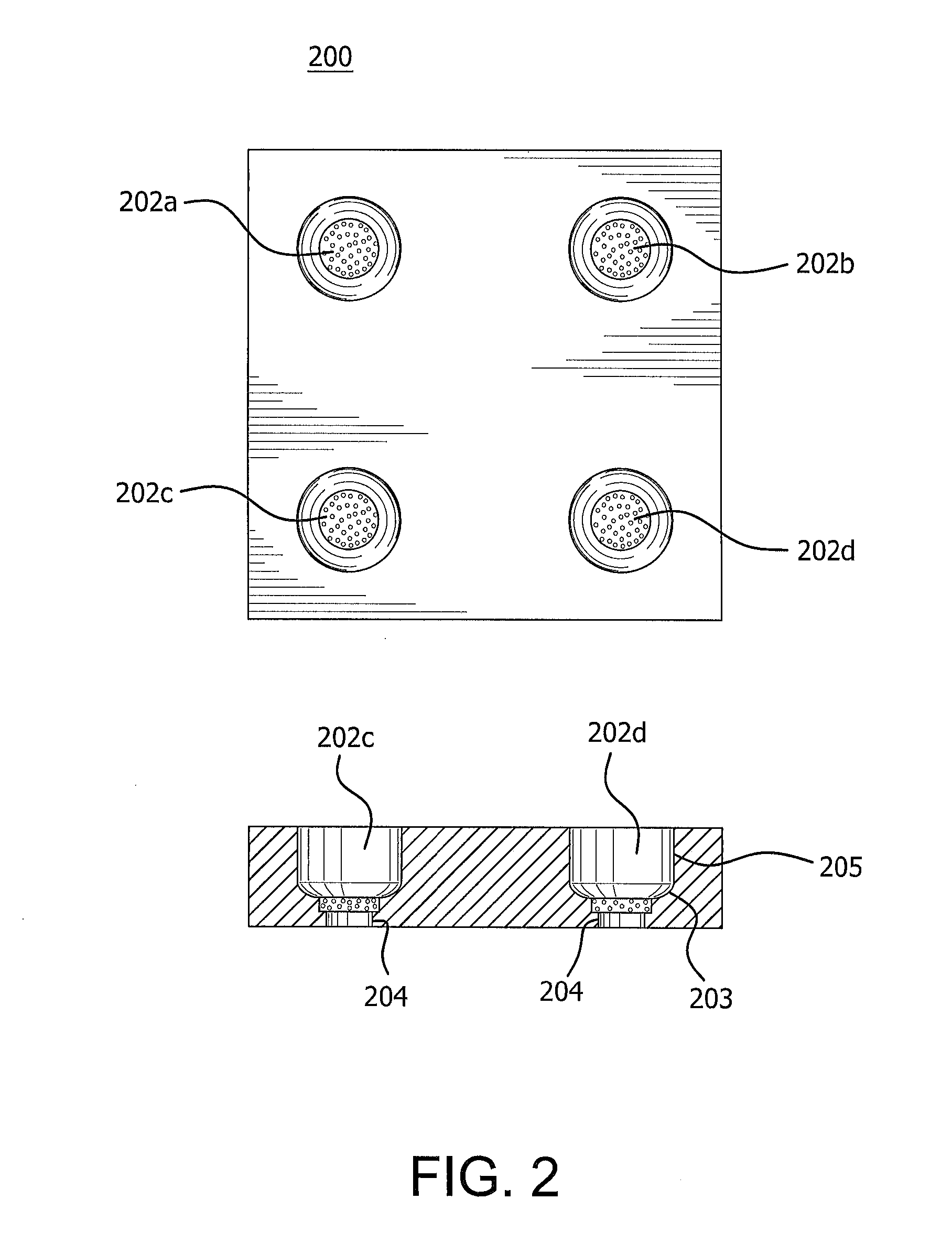
[0082]A barrier was created from a single densified ePTFE film 1.7-1.8 mil thick, which was obtained by the process described in U.S. Pat. No. 7,521,010 to Kennedy, et al. The film (104) was placed in the thermoforming equipment as depicted in FIG. 1 using the mold depicted in FIG. 2. The thermoforming equipment (100) uses hot air to heat the mold (200), and the pressure drop through the apparatus supplies the force to form the material. The mold has round cavities (202a-d) having different dimensions. One of 0.380 inches, one of 0.372 inches, one of 0.365 inches, and one of 0.358 inches. The bottom portion of the cavities have a rounded corner (203) with a radius of 0.079 inches, a side straight wall 205 of 0.188 inch height, and contain a 0.201 inch wide, 2 micron porous stainless steel disc (204) at its bottom most point.

[0083]At room temperature a pressure of 5 psi was applied. The heater on the hot air system (102) (Osram Sylvania 6000 W, 240V, 25 A) was activated using a setpo...

example 3

[0092]A sample was prepared in a manner similar to Example 2 except that the densified ePTFE barrier was formed to shape using a faster pressure ramp rate. The procedure of Example 2 was followed except that a pressure ramp rate of approximately 3 psi / minute from 5 psi to 18 psi was chosen. This ramp rate was obtained by closing only the exit air valve (112). This molding procedure resulted in a barrier film with milky appearance, which may indicate that there was some porosity induced in the material by the speed of the forming process.

[0093]The mold cavity was then filled with elastomer, molded and attached to a syringe stopper according to the process described in Example 2. After insertion into a glass syringe barrel the sample was tested.


PUM

PropertyMeasurementUnit
thicknessesaaaaaaaaaa

Abstract

A container having a barrier layer is provided. The container may be of thermoplastic and the barrier may inhibit materials from leaching from the thermoplastic material or from extraction of compounds from medicants by the thermoplastic. A process is also described that allows for molding thin barrier layers as container lines and for forming thermoplastic containers with barrier liners.

Description

RELATED APPLICATIONS[0001]The present application is a continuation-in-part application based on co-pending U.S. patent application Ser. No. 12 / 915,850, filed Oct. 29, 2010, which claims the benefit of Provisional No. 61 / 256,156, filed Oct. 29, 2009, the subject matter of which is specifically incorporated herein by reference.BACKGROUND OF THE INVENTION[0002]Syringes used for delivery of medicaments are principally constructed of a barrel and a stopper. The stopper is slidably fitted within the syringe barrel and may have a stopper rod affixed to it for actuation of the syringe and delivery of medicament. The stopper is generally constructed of an elastomer, with silicone oil applied. The silicone oil is applied to reduce sliding friction between the stopper and barrel and to improve the seal between them. The oil allows for ease of sliding when administering a dose which may ensure the full dose can be administered. Partial dosing is of particular concern in the case of pens and so...

Claims


Application Information

Patent Timeline
Patent Type & Authority Applications(United States)
IPC IPC(8): B32B1/02B32B15/085B32B37/02B32B27/32B29C65/70B32B7/02B32B17/10
CPCY10T428/1376A61M2207/00A61M5/3202Y10T428/1321A61M2005/3118Y10T156/1043Y10T428/1359A61M5/31513A61M2005/3131Y10T428/1352Y10T428/24992Y10T428/3154A61J1/1468
Inventor ASHMEAD, EDGAR G.GUNZEL, EDWARD C.MORITZ, MICHAEL P.
Owner WL GORE & ASSOC INC
Why Eureka
Try Eureka