
Micromechanical system and corresponding manufacturing method

a micromechanical system and manufacturing method technology, applied in the direction of microstructural devices, instruments, transportation and packaging, etc., can solve the problems of mechanical stability of connection, mechanical tension, and difficulty in manufacturing structures at high resolution, and achieve stable mechanical connection, low topography, and reliable removal of the sacrificial layer

Active Publication Date: 2012-10-04
ROBERT BOSCH GMBH
View PDF1 Cites 0 Cited by
  • Summary
  • Abstract
  • Description
  • Claims
  • Application Information

AI Technical Summary

Benefits of technology

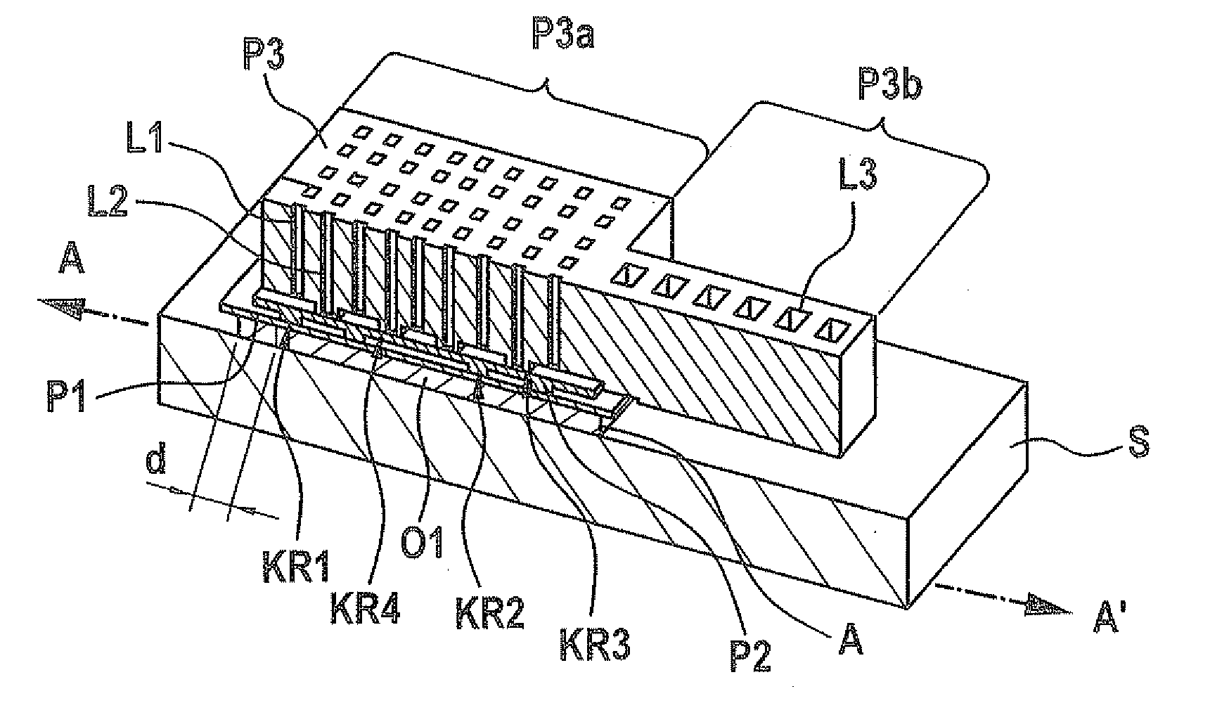
[0008]The exemplary embodiments and / or exemplary methods of the present invention have the advantage that it allows contact attachments, which are mechanically stable, to be manufactured on the substrate, a low topography to be produced simultaneously, also in the case of high sacrificial layer thicknesses, and above all a micromechanical system to be provided, which may avoid all undesirable oxide areas below the lowermost functional layer.
[0009]One aspect of the exemplary embodiments and / or exemplary methods of the present invention is not to produce a continuous planar connection between the functional layers, but rather to connect the functional layers to one another via weblike anchoring structures. These weblike anchoring structures may have a web ring structure and / or a web line structure of arbitrary geometry, for example. The width of the webs and their spaces are selected in such a way that, on the one hand, a stable mechanical connection may be achieved in consideration of the intended area of application and, on the other hand, reliable removal of the sacrificial layer from the spaces between the individual web sections may be ensured. The weblike anchoring structures may be designed as sufficiently narrow that a low topography forms on the surface of the web segments.
[0010]The first weblike anchoring structure between the first functional area of the first functional layer and the second functional area of the second functional layer and the second weblike anchoring structure between the second functional area of the second functional layer and the third functional area of the third functional area need have no overlap or only intersection-like overlaps. This has a very advantageous effect on the stability, since the topographies of the two contact planes only act marginally or not at all.
[0011]Two types of etching holes may be provided in the third functional area of the third functional layer. First etching holes are situated laterally offset on the second weblike anchoring structure and extend up to the third sacrificial layer. Second etching holes are situated over the second weblike anchoring structure and extend through the second weblike anchoring structure up to the second sacrificial layer. Depending on the process, it may prove to be favorable to design the second etching holes as wider than the weblike anchoring structure situated underneath, so that the third oxide layer virtually acts as a self-adjusting mask. By providing these two types of etching holes, both a tight arrangement of the web segments of the anchoring structures and also simultaneously a tight arrangement of the etching accesses may be achieved.
[0012]Narrow weblike anchoring structures may be used if the third functional area only receives slight polishing or no polishing or if in general a low topography is desirable or advantageous. Oblong second contact holes which extend perpendicularly to the web segments are particularly favorable, whereby process variations, such as adjustment errors, etching errors, etc., may be well compensated for.

Problems solved by technology

If connections are applied between the layers, a tall topology is created on the surface, which makes it more difficult to manufacture structures at high resolution.
The smaller the contact surfaces are designed, the less the influences by the elevated topography; however, the mechanical stability of the connection is thus simultaneously greatly reduced.
On the other hand, mechanical tensions may occur due to the different mechanical parameters, however, which may also change with the temperature.
Furthermore, depending on the geometry, it may be more or less difficult to completely remove the oxides between the polysilicon layers during the sacrificial layer etching process.

Method used


Image

  • Micromechanical system and corresponding manufacturing method
  • Micromechanical system and corresponding manufacturing method
  • Micromechanical system and corresponding manufacturing method

Examples


Embodiment Construction

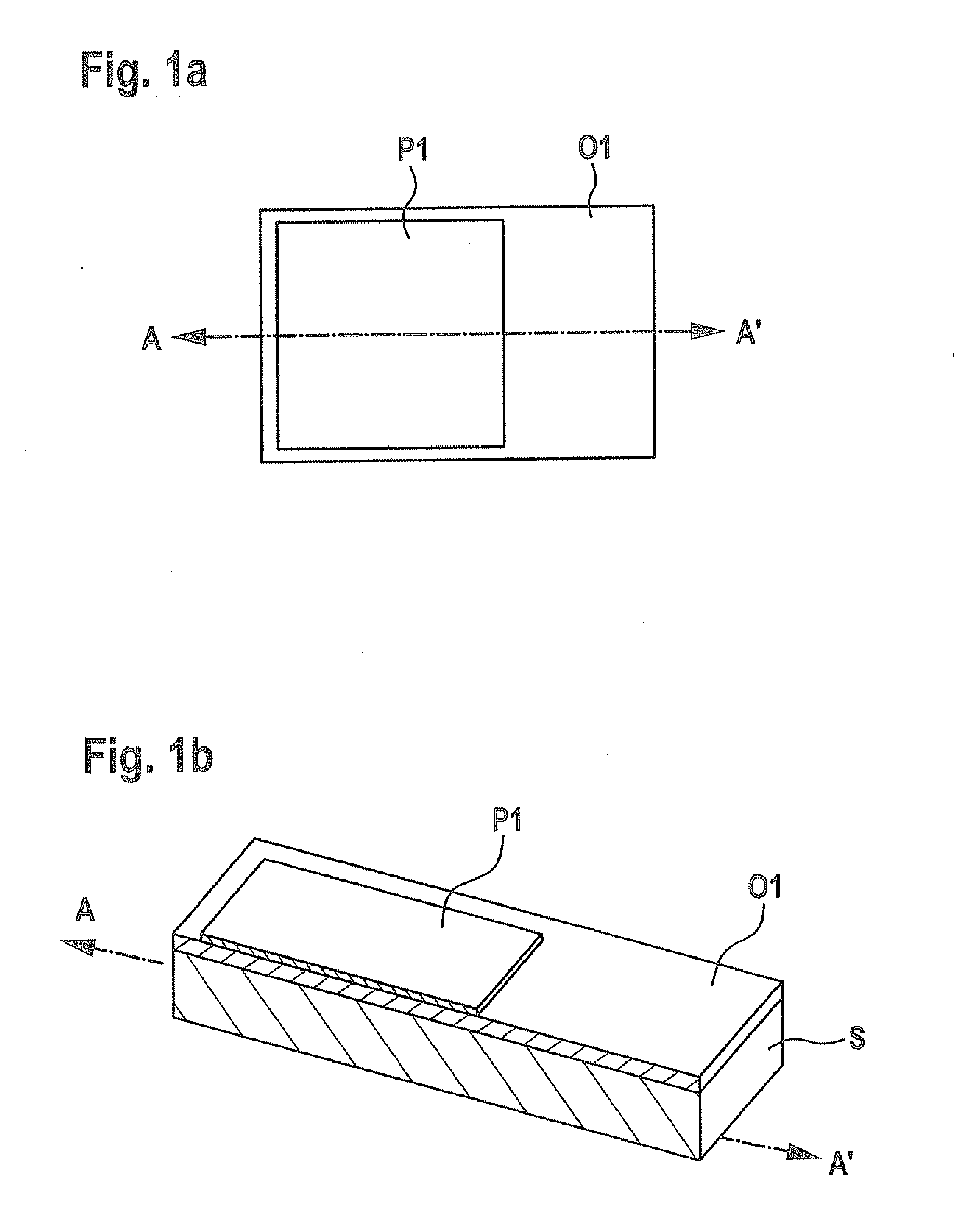
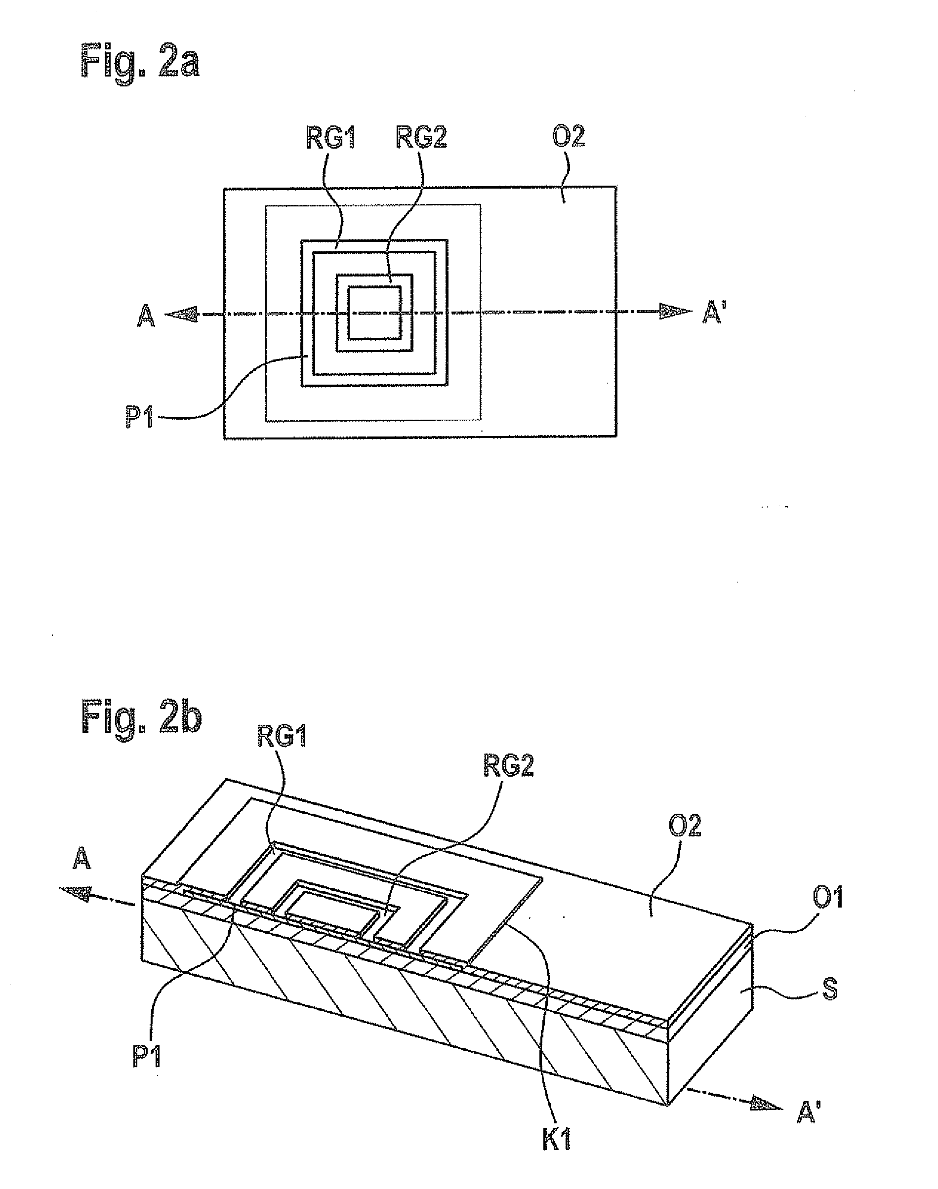
[0017]FIGS. 1a, b through FIGS. 6a, b show successive processing stages of a first specific embodiment of a method for manufacturing a micromechanical system according to the present invention, a) each in a top view and b) each in section along line AA′ in a).

[0018]In FIG. 1, reference sign S identifies a silicon substrate, for example, a wafer substrate. A first sacrificial layer O1 made of oxide is provided by deposition, for example, on silicon substrate S. P1 identifies a first micromechanical functional area made of polysilicon, which has been structured on first sacrificial layer O1.

[0019]Furthermore, with reference to FIG. 2, a second sacrificial layer O2 made of oxide is deposited over first micromechanical functional area P1 and surrounding first sacrificial layer O1, which forms a step K1 on first micromechanical functional area P1.

[0020]Subsequently, a first weblike trench structure RG1, RG2 is formed in second sacrificial layer O2 over first micromechanical functional ar...


PUM

PropertyMeasurementUnit
micromechanical functional areaaaaaaaaaaa
micromechanical functional areasaaaaaaaaaa
thickaaaaaaaaaa

Abstract

A micromechanical system is described having a substrate; a first micromechanical functional area, which is situated above the substrate; a second micromechanical functional area, which is situated above the first micromechanical functional area and is connected via a first weblike anchoring structure to the first micromechanical functional area; a third micromechanical functional area, which is situated above the second micromechanical functional area, and which has a first subarea and a second subarea; the first subarea being connected via a second weblike anchoring structure to the second micromechanical functional area; and the second subarea being mounted floating over the substrate by the first subarea. The invention also provides a method for manufacturing such a micromechanical system.

Description

RELATED APPLICATION INFORMATION[0001]The present application claims priority to and the benefit of German patent application no. 10 2011 006 403.6, which was filed in Germany on Mar. 30, 2011, the disclosure of which is incorporated herein by reference.FIELD OF THE INVENTION[0002]The present invention relates to a micromechanical system and a corresponding manufacturing method, in particular for use in micromechanical acceleration sensors, yaw rate sensors, and the like.BACKGROUND INFORMATION[0003]Situating a thick polysilicon functional layer over a thin buried polysilicon layer is generally known for manufacturing MEMS structures. The buried polysilicon layer is used in this case as a printed conductor or an electrode. The polysilicon functional layer is typically exposed via a trenching process and a sacrificial layer etching method.[0004]A micromechanical system and a corresponding manufacturing method are known from DE 10 2007 060 878 A1, a second buried polysilicon layer being...

Claims


Application Information

Patent Timeline
Patent Type & Authority Applications(United States)
IPC IPC(8): B32B7/14B44C1/22
CPCB81B2207/07Y10T428/24851G01P15/0802B81C1/00039
Inventor REINMUTH, JOCHENSCHEURLE, ANDREASBIERHOFF, CHRISTIAN
Owner ROBERT BOSCH GMBH
Learn More