

Fabric composite support or enclosure for an automotive battery pack
- Summary
- Abstract
- Description
- Claims
- Application Information
AI Technical Summary
Benefits of technology
Problems solved by technology
Method used
Image

Examples
Embodiment Construction
[0025]The following description of the embodiment(s) is merely exemplary in nature and is not intended to limit the invention, its application, or uses.
[0026]Vehicles propelled by electric motors are becoming more widespread as more manufacturers supplement their product lines with hybrid or all-electric vehicles. Such vehicles incorporate a high voltage battery or battery pack as an energy storage device, the battery being suitably sized to provide capability for all-electric vehicle operation over some predetermined range.
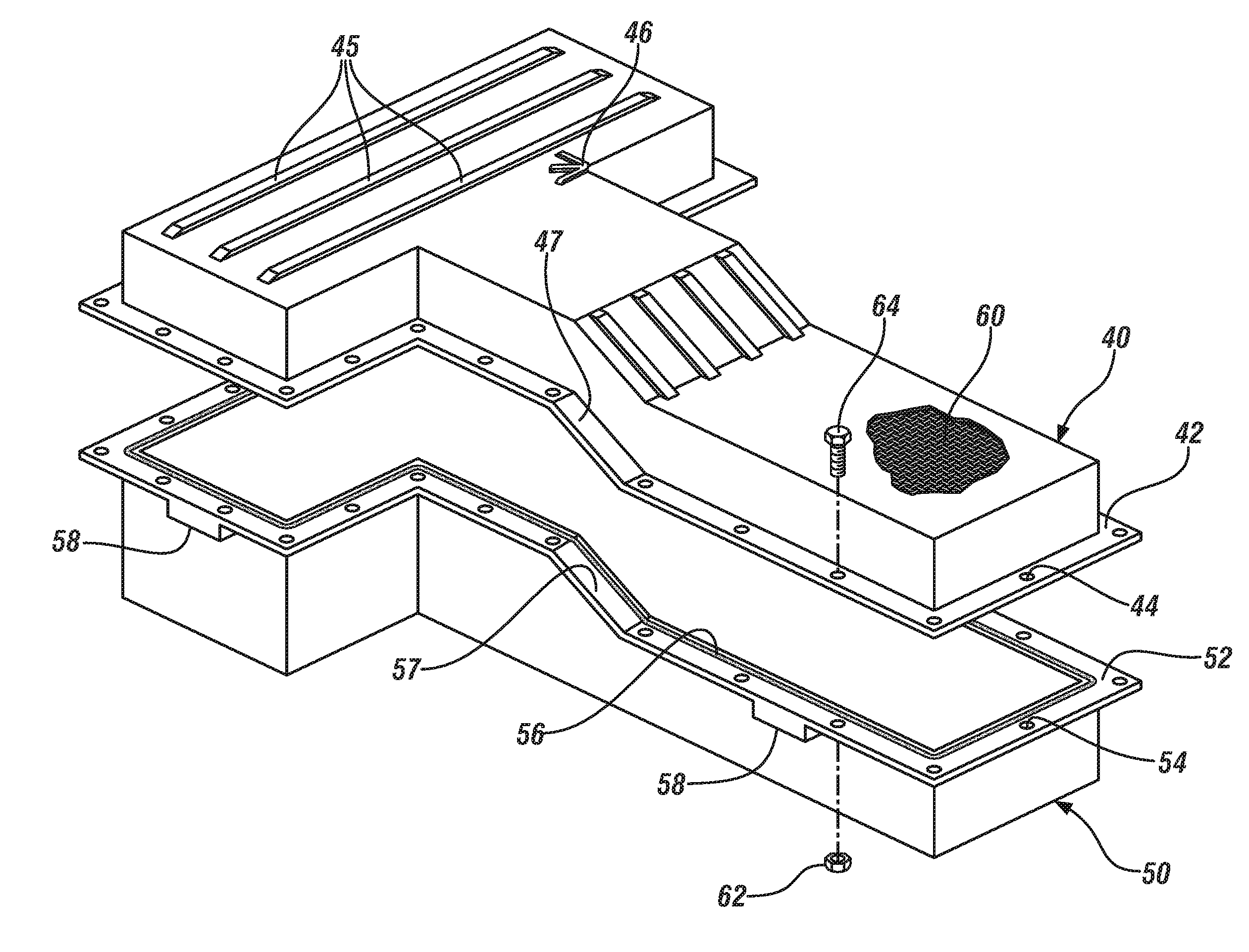
[0027]These battery packs may range in weight from about 30 Kg to about 200 Kg and, when installed in a vehicle, are typically located in an enclosure. The enclosure is generally fabricated as two parts, a support structure, resembling a tray, with cavity geometry complementary to the exterior geometry of the battery pack, and a cover, which when joined to the support structure completes the enclosure. The interior cavity walls of at least the support, and, prefe...
PUM
 Abstract
Description
Claims
Application Information