
Polishing method, manufacturing method of piezoelectric vibrating piece, piezoelectric vibrator, oscillator, electronic apparatus and radio-controlled timepiece

a manufacturing method and piezoelectric technology, applied in the field of polishing methods, can solve the problems of inability to enhance the thickness accuracy the method is not applicable to the polishing so as to achieve the enhancement of the rotational balance of the carrier in rotation and revolution, the reduction of irregular thickness of the tuning fork forming wafer among the plurality of carriers, and the reduction of the thickness of the tuning fork

Inactive Publication Date: 2012-10-04
SII CRYSTAL TECH
View PDF10 Cites 7 Cited by
  • Summary
  • Abstract
  • Description
  • Claims
  • Application Information

AI Technical Summary

Benefits of technology

[0014]The present invention has been made in view of the above-mentioned circumstances, and it is an object of the present invention to provide a polishing method which can enhance thickness accuracy of a wafer at the time of polishing the wafer, a manufacturing method of a piezoelectric vibrating piece, a piezoelectric vibrator, an oscillator, an electronic apparatus and a radio-controlled timepiece.

Problems solved by technology

The above-mentioned method pertaining to the related art gives rise to a drawback that the method is not applicable to polishing of a tuning fork forming wafer which vibrates in a bending mode.
However, as in the case of this measuring device, when a measuring terminal is brought into contact with a suitable part of the polishing device, the measuring position becomes the same point and hence, wear occurs thus giving rise to a drawback that thickness accuracy of a tuning fork forming wafer cannot be enhanced.

Method used


Image

  • Polishing method, manufacturing method of piezoelectric vibrating piece, piezoelectric vibrator, oscillator, electronic apparatus and radio-controlled timepiece
  • Polishing method, manufacturing method of piezoelectric vibrating piece, piezoelectric vibrator, oscillator, electronic apparatus and radio-controlled timepiece
  • Polishing method, manufacturing method of piezoelectric vibrating piece, piezoelectric vibrator, oscillator, electronic apparatus and radio-controlled timepiece

Examples


Embodiment Construction

[0050]Hereinafter, the explanation is made with respect to a polishing method, a manufacturing method of a piezoelectric vibrating piece, a piezoelectric vibrator having a piezoelectric vibrating piece manufactured by the manufacturing method of a piezoelectric vibrating piece, an oscillator having the piezoelectric vibrator, an electronic apparatus, and a radio-controlled timepiece according to one embodiment of the present invention.

[0051]Hereinafter, embodiments of the present invention are explained in conjunction with drawings.

(Piezoelectric Vibrator)

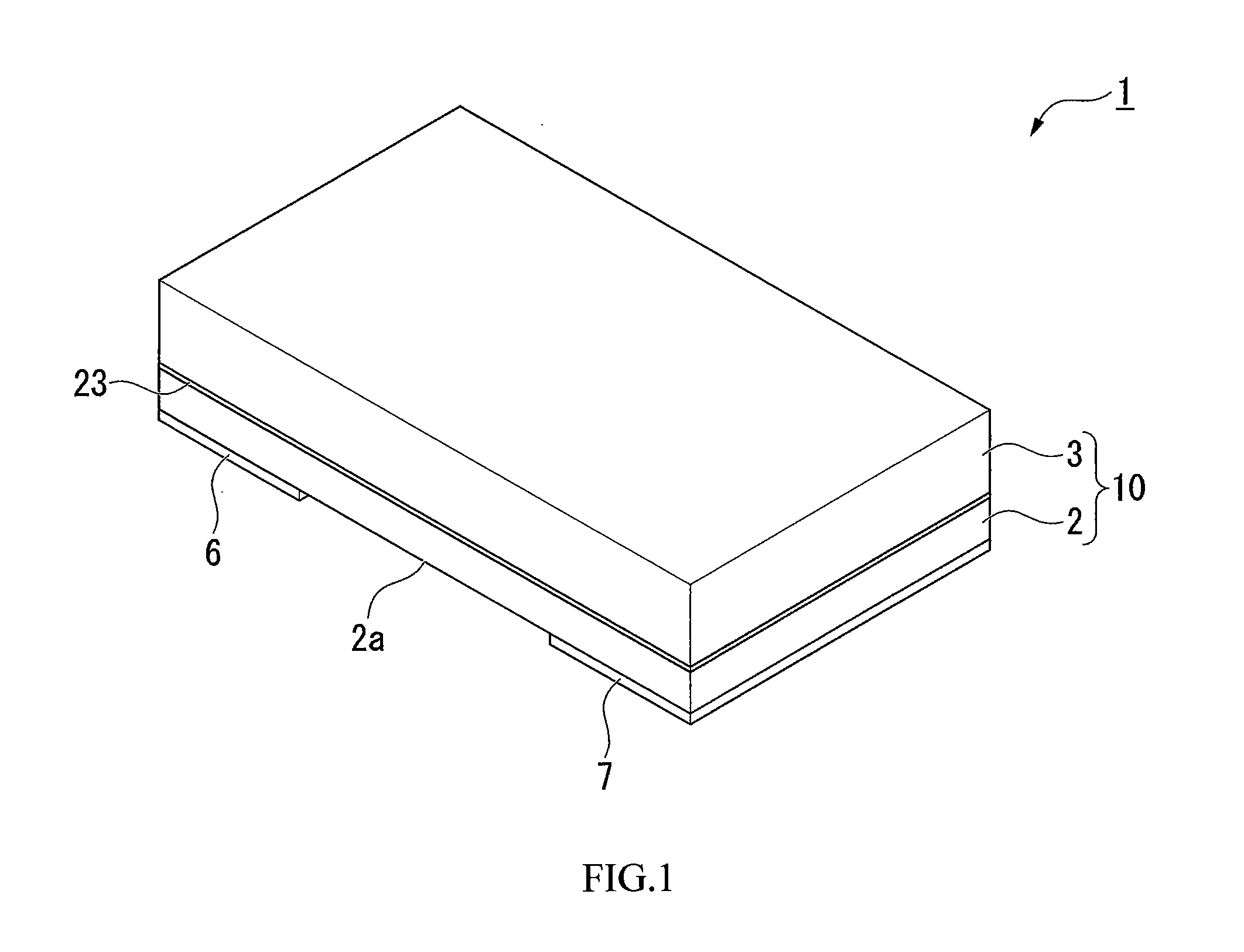
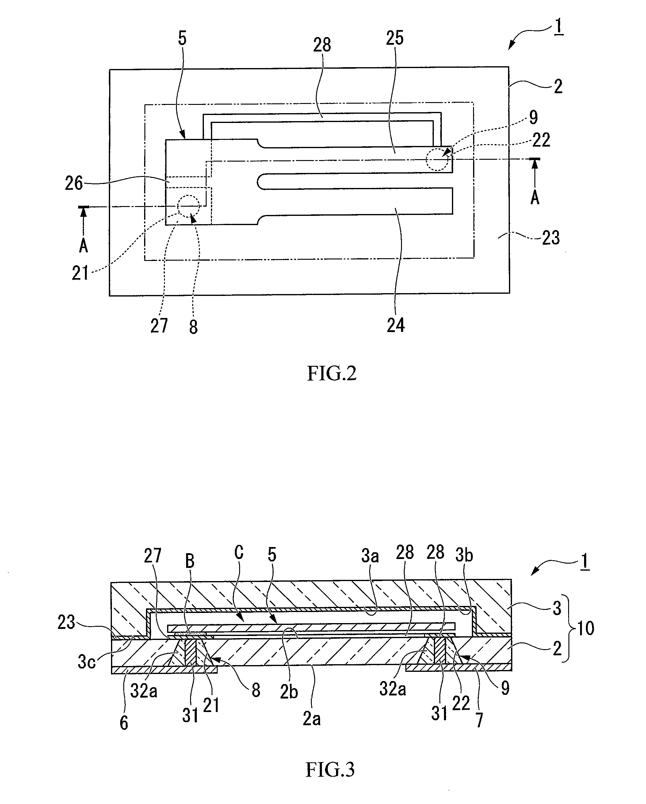
[0052]FIG. 1 is an appearance perspective view of a piezoelectric vibrator according to this embodiment as viewed from a lid substrate side. FIG. 2 is an internal constitutional view of the piezoelectric vibrator, and is also a view of a piezoelectric vibrating piece as viewed from above in a state where the lid substrate is removed.

[0053]Further, FIG. 3 is a cross-sectional view of the piezoelectric vibrator taken along a line A-A...


PUM

PropertyMeasurementUnit
timeaaaaaaaaaa
flow rateaaaaaaaaaa
voltageaaaaaaaaaa

Abstract

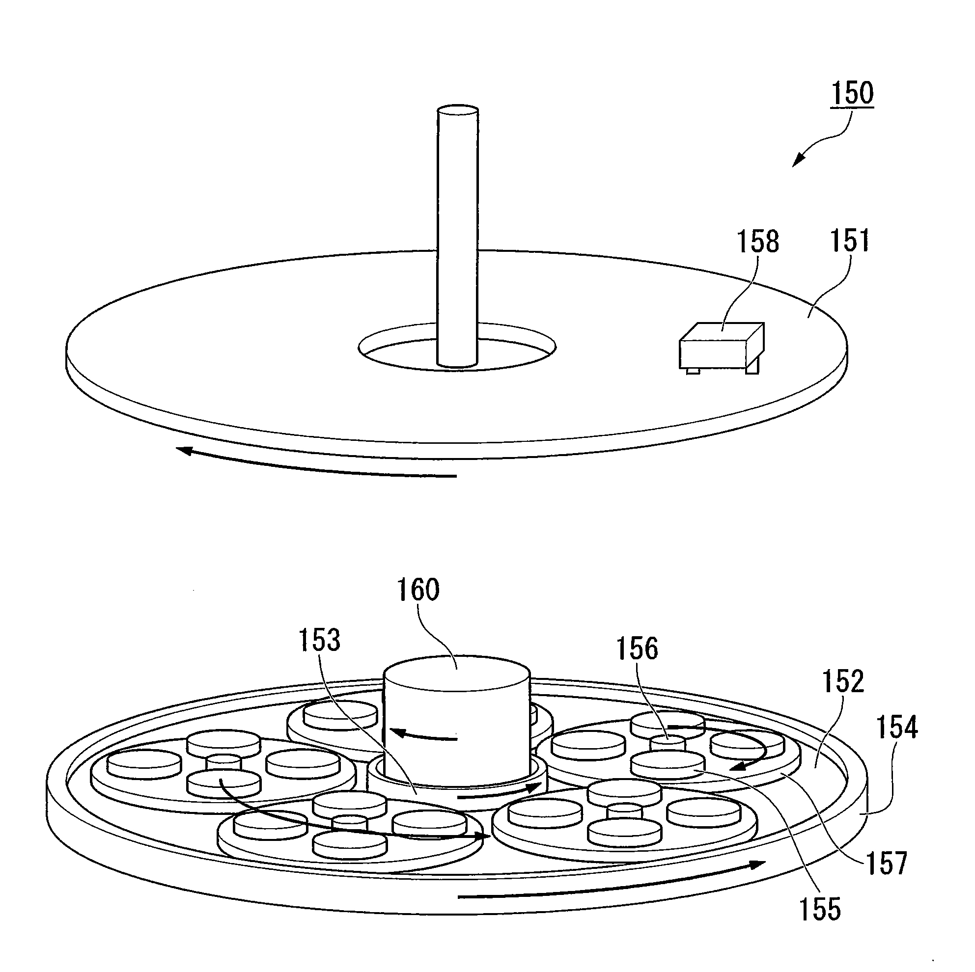
Provided is a polishing method which can enhance thickness accuracy of a wafer at the time of polishing the wafer. In a polishing method of a crystal wafer (tuning fork substrate) which is held on a carrier between an upper platen and a lower platen, an AT cut wafer for thickness measurement is arranged on the carrier, the AT cut wafer is polished together with the crystal wafer (tuning fork substrate), resonance frequency of the AT cut wafer is detected, and a thickness of the crystal wafer (tuning fork substrate) is controlled based on a detection result.

Description

RELATED APPLICATIONS[0001]This application claims priority under 35 U.S.C. §119 to Japanese Patent Application No. 2011-070538 filed on Mar. 28, 2011, the entire content of which is hereby incorporated by reference.BACKGROUND OF THE INVENTION[0002]1. Field of the Invention[0003]The present invention relates to a polishing method, a manufacturing method of a piezoelectric vibrating piece, a piezoelectric vibrator having a piezoelectric vibrating piece manufactured by the manufacturing method of a piezoelectric vibrating piece, an oscillator having the piezoelectric vibrator, an electronic apparatus, and a radio-controlled timepiece.[0004]2. Description of the Related Art[0005]Recently, a package product having the following constitution has been popularly used. The package product includes a base substrate and a lid substrate which are bonded to each other by anodic bonding in a laminated state and form a cavity therebetween, and an operating piece which is mounted on a portion of th...

Claims


Application Information

Patent Timeline
Patent Type & Authority Applications(United States)
IPC IPC(8): B24B1/00B24B49/06H01L41/22H01L41/311H01L41/313H01L41/337
CPCG04R20/10B24B37/042H03H2003/0492H03H9/1021H03H9/215B24B37/08
Inventor FUJIHIRA, YOUICHI
Owner SII CRYSTAL TECH
Learn More