Guidewire

Inactive Publication Date: 2012-10-04
ASAHI INTECC CO LTD
View PDF8 Cites 6 Cited by
  • Summary
  • Abstract
  • Description
  • Claims
  • Application Information

AI Technical Summary

Benefits of technology

[0007]When the distal end portion of the guidewire having the above-described structure has a shape having a third curvature after the core shaft and the coil body have been coupled to each other, the third curvature of the shape of the distal end portion of the core shaft is greater than the first curvature of the shape of the distal end portion of the core shaft prior to coupling thereof to the coil body (that is, the distal end portion of the core shaft is deformed into a shape having a tighter curve than it had prior to assembly), whereas the third curvature of the shape of the distal end portion of the coil body becomes less than the second curvature of the shape of the distal end portion of the coil body prior to coupling thereof to the core shaft (that is, the distal end portion of the coil body is deformed into a more linear shape

Problems solved by technology

However, when the distal end portion of the guidewire during use is elastically deformed into a linear shape, what is called “

Method used


Image

  • Guidewire
  • Guidewire
  • Guidewire

Examples


Embodiment Construction

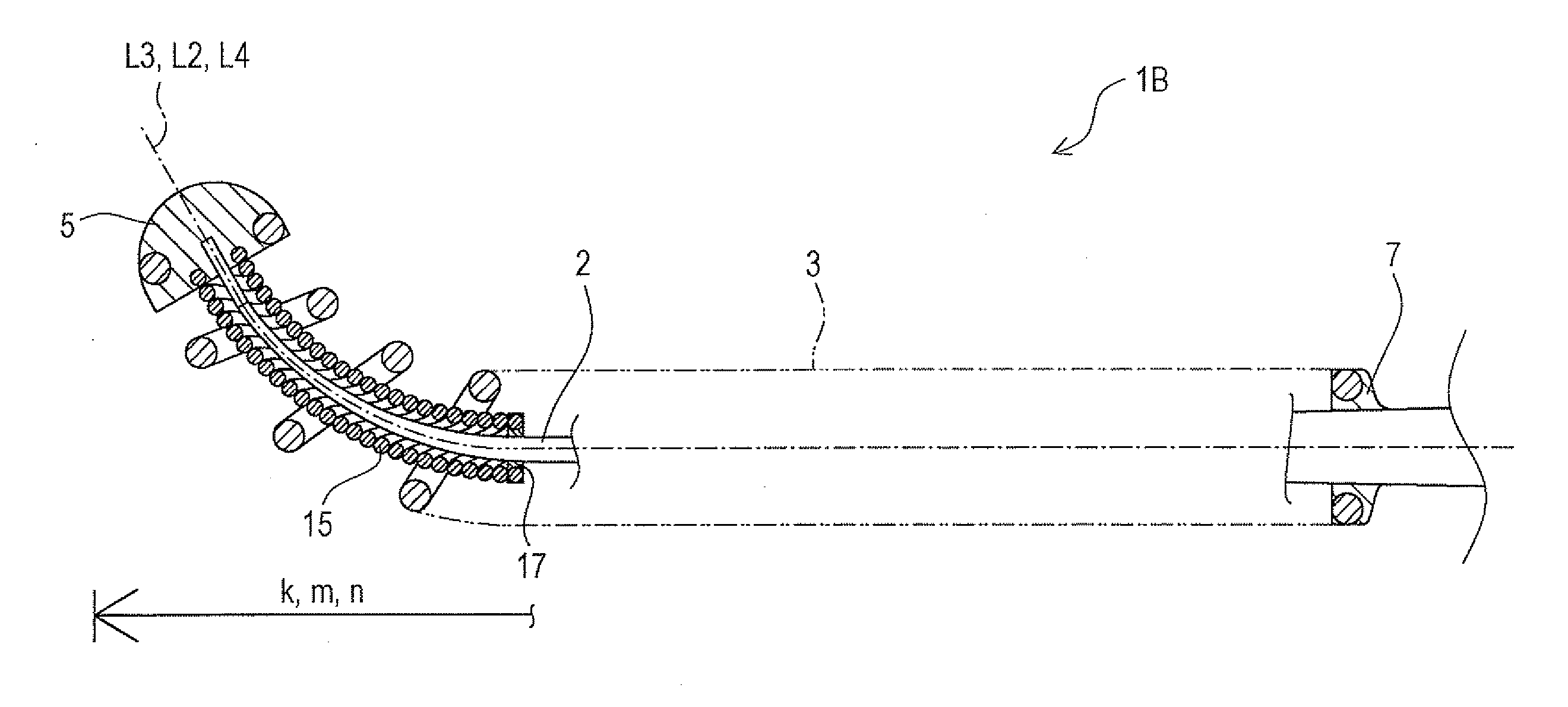
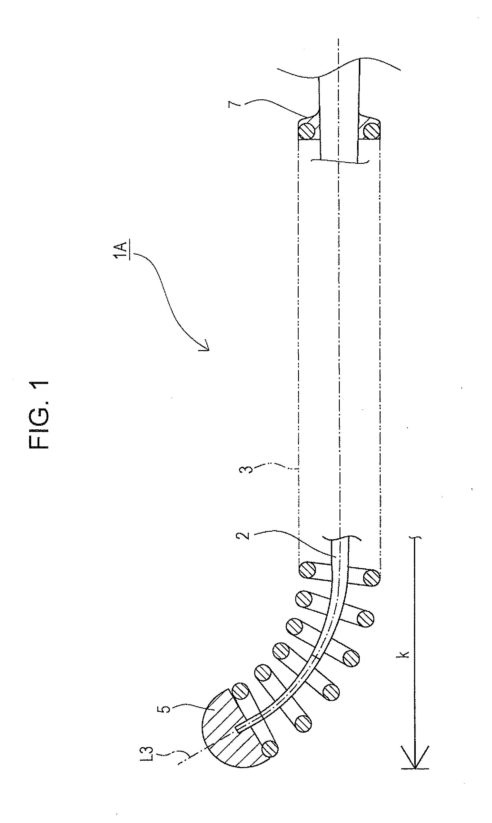
[0017]As shown in FIG. 1, a guidewire 1A includes a core shaft 2 and a coil body 3, which are coupled to each other. To increase maneuverability of the guidewire, a distal end portion k has a curved shape.

[0018]First, an external shape of the core shaft 2 and an external shape of the coil body 3 will be described in detail.

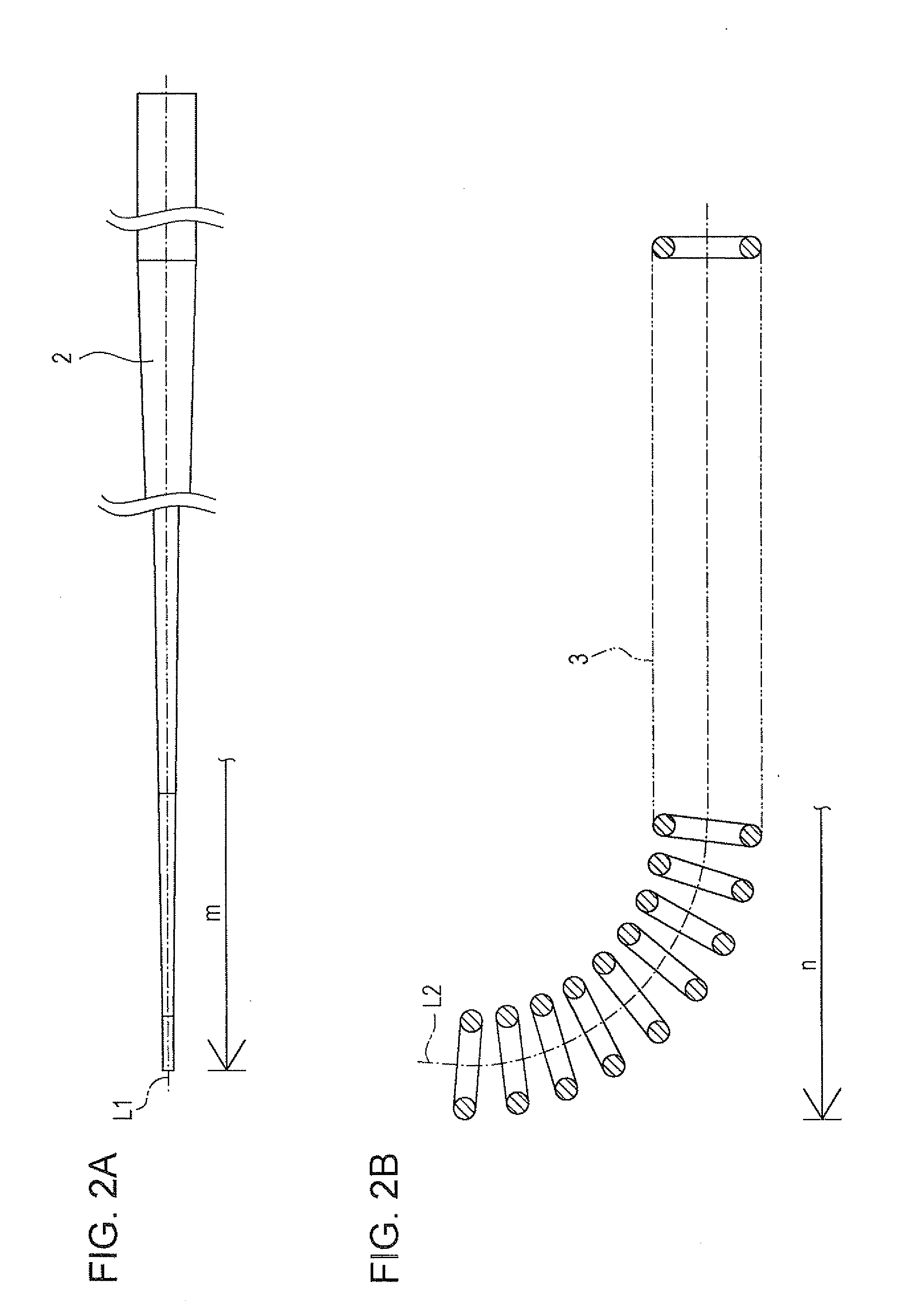
[0019]As shown in FIG. 2A, prior to coupling, the core shaft 2 has the shape of a tapered round bar whose distal-end side has a small diameter and whose proximal-end side has a larger diameter, and has what is called a linear shape over its entire length. That is, along a center line L1 in a longitudinal-axis direction of the core shaft 2, a curvature X1 at least at a distal end portion m is equal to zero (X1=0) with respect to a proximal end of the core shaft 2. That is, the core shaft 2 has a substantially linear (straight line) shape prior to coupling the core shaft 2 to the coil body 3.

[0020]As shown in FIG. 2B, the coil body 3 is sparsely wound, and at least ...


PUM


Abstract

A guidewire includes a core shaft and a coil body that covers at least a distal end portion of the core shaft. Along a center line in a longitudinal-axis direction of the core shaft, the distal end portion of the core shaft has a first pre-assembly curvature with respect to a proximal end of the core shaft. Along a center line in a longitudinal-axis direction of the coil body, at least a distal end portion of the coil body has a second pre-assembly curvature with respect to a proximal end of the coil body. The first pre-assembly curvature is less than the second pre-assembly curvature. When the core shaft and the coil body are coupled to each other, a distal end portion of the guidewire has, along a center line in a longitudinal-axis direction of the guidewire, a third curvature with respect to a proximal end of the guidewire.

Description

CROSS-REFERENCE TO RELATED APPLICATION[0001]This application claims priority to Japanese Patent Application No. 2011-074103 filed in the Japan Patent Office on Mar. 30, 2011, the entire contents of which are incorporated herein by reference.BACKGROUND[0002]The disclosed embodiments relate to a medical device. More specifically, the disclosed embodiments relate to a guidewire. A guidewire is used as a guide when inserting a catheter into, for example, a blood vessel, a ureter, or an organ, or when inserting an indwelling device into an aneurysm of a blood vessel. Ordinarily, the guidewire includes a core shaft (core wire) and a coil body (coil) that is wound around an outer surface of a distal end portion of the core shaft. A distal end portion of the coil body and the distal end portion of the core shaft are joined to each other to form a tip portion.[0003]Further, in order to increase maneuverability when reaching a side branch of a blood vessel, a distal end of the guidewire may b...

Claims


Application Information

Patent Timeline
IPC IPC(8): A61M25/09
CPCA61M25/09A61M2025/09175A61M2025/09108A61M2025/09083
Inventor TSUNEZUMI, ATSUSHI
Owner ASAHI INTECC CO LTD
Why Eureka
Try Eureka