Cooling structure, gas turbine combustor and manufacturing method of cooling structure

a technology of cooling structure and gas turbine, which is applied in the direction of machines/engines, lighting and heating apparatus, applications, etc., can solve the problems of manufacturing cost, and achieve the effect of high cooling efficiency without increasing manufacturing cos

Inactive Publication Date: 2012-10-11
MITSUBICHI HEAVY IND AERO ENGINES LTD
View PDF29 Cites 28 Cited by
  • Summary
  • Abstract
  • Description
  • Claims
  • Application Information

AI Technical Summary

Benefits of technology

[0015]According to the present invention, the cooling structure, the gas turbine combustor, and the method of manufacturing the cooling structure are provided to attain a high cooling efficiency without increasing the manufacturing cost.

Problems solved by technology

To prevent generation of the space, a high manufacture precision is required in case of manufacturing the plurality of pin fins 102, which is disadvantage from the point of a manufacturing cost.

Method used


Image

  • Cooling structure, gas turbine combustor and manufacturing method of cooling structure
  • Cooling structure, gas turbine combustor and manufacturing method of cooling structure
  • Cooling structure, gas turbine combustor and manufacturing method of cooling structure

Examples


first embodiment

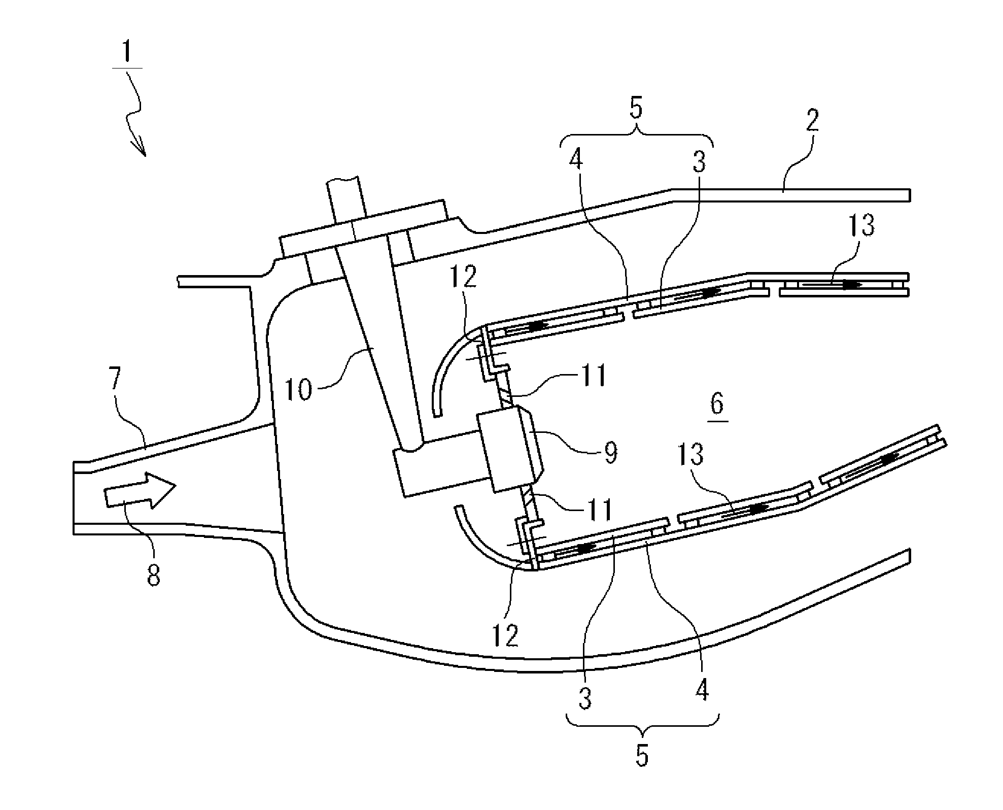
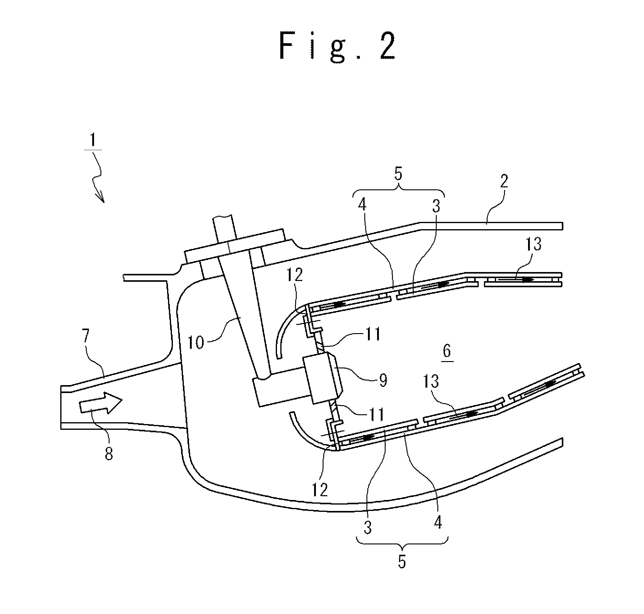
[0032]FIG. 2 is a diagram showing a gas turbine combustor 1 according to an embodiment of the present invention. In the gas turbine combustor 1, compressed air is taken in from a compressor (not shown) and fuel is supplied into the compressed air for combustion. Thus, a combustion gas is generated, and is supplied to a turbine (not shown). Thus, the turbine is driven. For example, the gas turbine combustor 1 is used for a gas turbine for aircraft.

[0033]As shown in FIG. 2, the gas turbine combustor 1 is provided with a combustor case 2, a combustor liner 5 and a fuel supply mechanism 10.

[0034]An air inlet 7 is provided for the combustor case 2. The compressed air 8 is supplied from the compressor (not shown) into the inside of the combustor case 2 through the air inlet 7.

[0035]The combustor liner 5 is arranged inside the combustor case 2. An internal space of the combustor liner 5 forms a combustion chamber 6. An air inlet 11 is provided for the combustor liner 5 and the compressed a...

second embodiment

[0067]Next, a second embodiment will be described. FIG. 9 is a diagram schematically showing the cooling structure according to the present embodiment. In the present embodiment, the configuration of the first surface 17 of the cooling panel 3 is changed from the first embodiment. Because the same configuration as in the first embodiment can be adopted for the other points, the detailed description is omitted.

[0068]As shown in FIG. 9, in the present embodiment, the first surface 17 is a flat plane. When each pin fin 15 is inclined along a direction of a flow of the cooling air 13, the cooling air 13 is turned to the cooling panel 3 due to each pin fin 15 and collides diagonally to the first surface 17. Therefore, it would be considered that the cooling efficiency becomes lower, comparing with the first embodiment. However, in the present embodiment, because the maximum allowable value of the clearance b is appropriately set, it is possible to restrain the manufacturing cost while ma...


PUM

PropertyMeasurementUnit
angleaaaaaaaaaa
angleaaaaaaaaaa
angleaaaaaaaaaa

Abstract

A cooling structure, a gas turbine combustor, and a method of manufacturing the cooling structure attain a high cooling efficiency without increasing manufacturing cost. The cooling structure includes a first member as a cooling object having a first plane, and a second member arranged above the first plane and having an opposing second plane such that a passage is formed between the first plane and the second plane for a cooling medium to flow. The first member has a plurality of prominences each of which extends upwardly from the first plane, and extends to be inclined along a direction in which the cooling medium flows. A clearance between the second plane and a tip of each prominence is set such that a heat transfer rate between the cooling medium and the first member becomes larger than that when each prominence extends vertically upward from the first plane.

Description

INCORPORATION BY REFERENCE[0001]This patent application claims a priority on convention based on Japanese Patent Application No. 2011-084582. The disclosure thereof is incorporated herein by reference.TECHNICAL FIELD[0002]The present invention is related to a cooling structure, a gas turbine combustor and a method of manufacturing the cooling structure.BACKGROUND TECHNIQUES[0003]In a combustor provided for a gas turbine, a cooling structure is provided as a wall structure of a combustion chamber. FIG. 1 is a diagram showing an example of such a cooling structure. The cooling structure shown in FIG. 1 is provided with a cooling panel 101 and a shell 103. The cooling panel 101 is arranged to oppose to the shell 103. Between the cooling panel 101 and the shell 103, a passage 104 is formed so as to pass a cooling air therethrough. Also, a plurality of pin fins 102 are provided for the cooling panel 101. The plurality of pin fins 102 are arranged in the passage 104 and extend upwardly in...

Claims


Application Information

Patent Timeline
Patent Type & Authority Applications(United States)
IPC IPC(8): F02C7/12F28F7/00B23P15/26
CPCF23R3/005Y10T29/49359Y02T50/675F23R2900/03045F28F3/022F28F3/048F28F13/12F28D2021/0078F23R3/002Y02T50/60
Inventor MIYAKE, YOSHIAKI
Owner MITSUBICHI HEAVY IND AERO ENGINES LTD
Why Eureka
Try Eureka