

Helicopter with cycloidal rotor system
a cycloid rotor and helicopter technology, applied in the direction of rotorcraft, vehicles, aircrafts, etc., can solve the problems of limited maximum horizontal speed of helicopter, lack of control freedom, and inability to fully control the fuselage and aircraft attitude of the pilot, so as to improve the horizontal speed of the helicopter and increase the surface roughness. , the effect of efficient thrust compounding
- Summary
- Abstract
- Description
- Claims
- Application Information
AI Technical Summary
Benefits of technology
Problems solved by technology
Method used
Image

Examples
Embodiment Construction
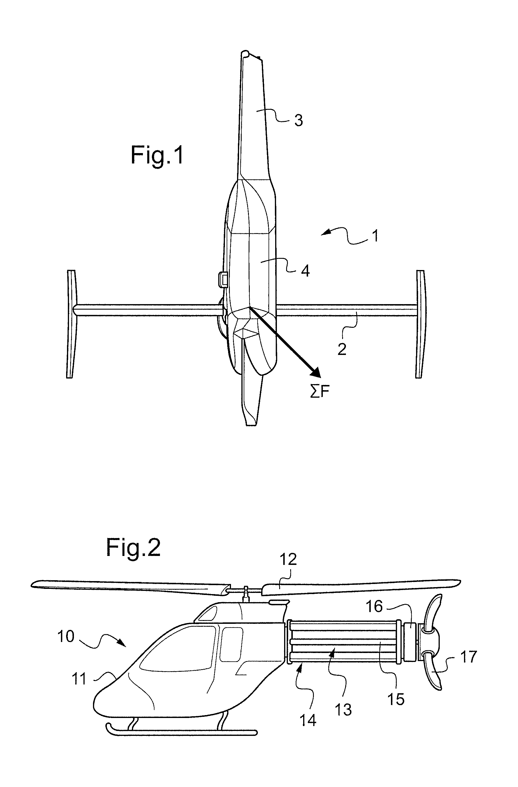
[0032]According to FIG. 1 an empennage 1 of a classical helicopter (not shown) comprises a fixed horizontal stabilizer 2, a fixed vertical fin 3 and a tail rotor 4. The horizontal stabilizer 2 generates a negative lift, the vertical fin 3 provides yaw stability and generates in forward flight part or all of the antitorque for the main rotor while the tail rotor 4 provides all of the antitorque force in hover condition and almost no additional force in cruise. □F indicates direction and amplitude of the resulting force at the empennage 1 said resulting force being principally directed vertical to a tail boom of said helicopter.
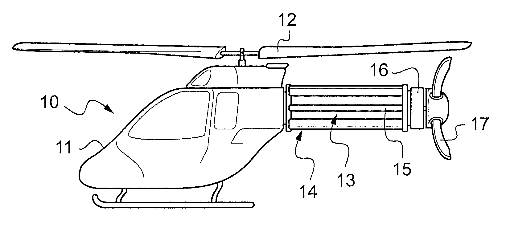
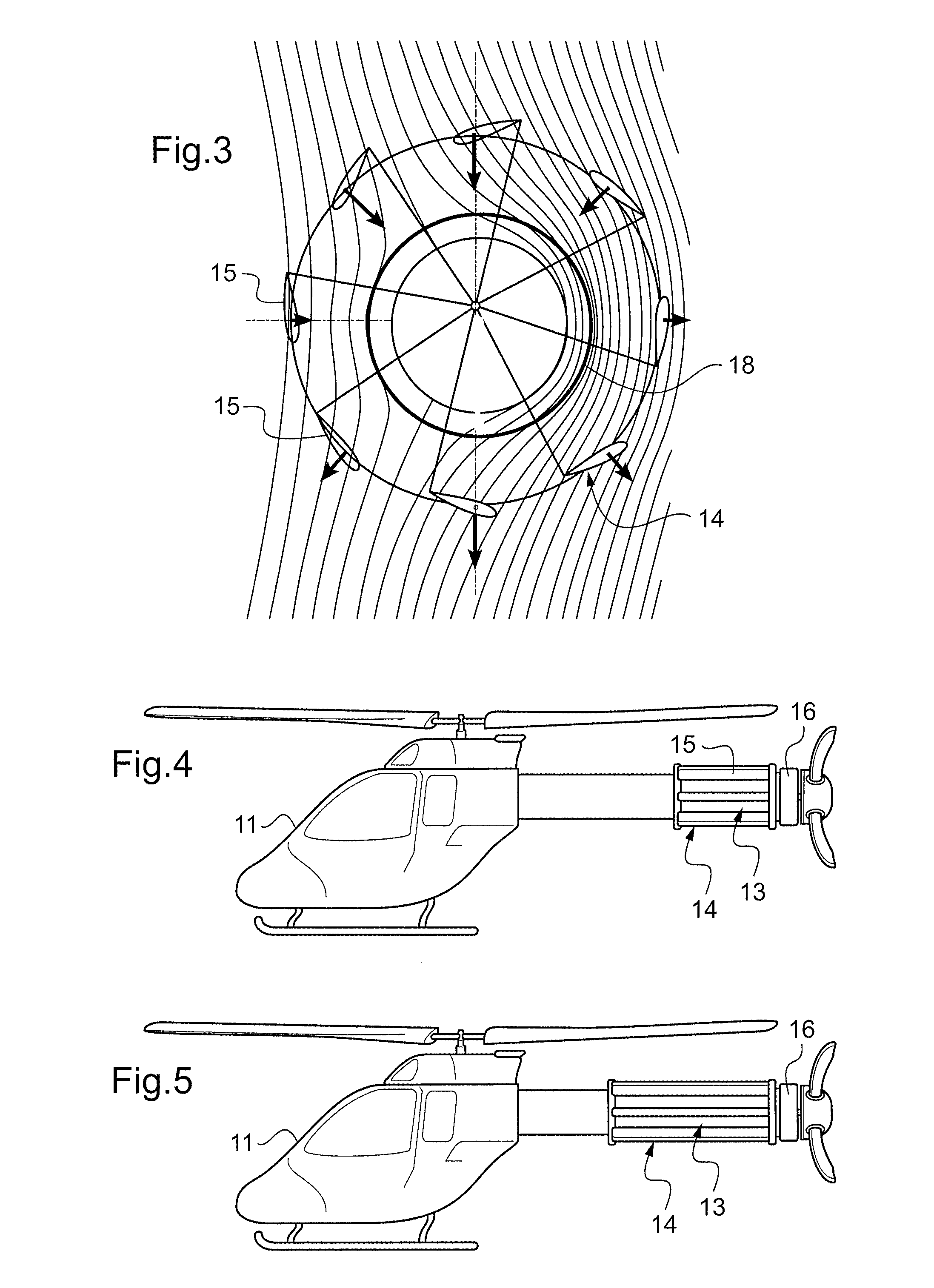
[0033]According to FIG. 2 the helicopter 10 has a fuselage 11 and is equipped with a main rotor 12. A tail boom 13 with a longitudinal axis is fixed to the fuselage 11. A cycloidal rotor 14 of individual blades 15 surrounds the tail boom 13 between the fuselage and its rear end 16, said blades 15 being essentially parallel to the longitudinal axis of the tail b...
PUM
 Abstract
Description
Claims
Application Information