Main Brake Cylinder for a Hydraulic Vehicle Brake System and Method for Operating Same

a brake system and hydraulic vehicle technology, applied in the direction of brake action initiation, brake systems, vehicle components, etc., can solve the problems of sudden changes in generator operation of electric machines is not possible, and the deceleration effect of electric machines cannot be achieved

Active Publication Date: 2012-10-11
ROBERT BOSCH GMBH
View PDF4 Cites 3 Cited by
  • Summary
  • Abstract
  • Description
  • Claims
  • Application Information

AI Technical Summary

Benefits of technology

[0020]Method claim 5 provides that for service braking, on activation of the master brake cylinder according to the invention, an electric machine of a motor vehicle fitted with the vehicle brake system is operated as a generator and the motor vehicle decelerated by this. Also the master brake cylinder is isolated from the vehicle brake system or from one (or more) brake circuit(s) of the vehicle brake system by closure of an isolating valve. In this brake circuit a wheel brake pressure is generated with a hydraulic pump and regulated such that a total deceleration effect of the electric machine operated as a generator and of the brake circuit isolated from the master brake cylinder and where applicable one or more further brake circuits is at least approximately as large as it would be on braking with the same activation force and / or same activation travel if the motor vehicle were decelerated exclusively by activation of the vehicle brake system with the master brake cylinder. Changes to the deceleration effect of the electric machine operated as a generator are regulated out so that this is as imperceptible as possible for the vehicle driver.

Problems solved by technology

One difficulty in such covering is that the deceleration effect of the electric machine operated as a generator depends on various circumstances and changes during braking.
A charge state of the accumulator is another such circumstance: if the accumulator is fully charged and therefore cannot receive any electric current, generator operation of the electric machine is not possible and the motor vehicle must be braked conventionally exclusively by the hydraulic vehicle brake system.
Shift processes also cause sudden changes in the deceleration effect of the electric machine operated as a generator if this is decoupled on decoupling the vehicle wheels.

Method used


Image

  • Main Brake Cylinder for a Hydraulic Vehicle Brake System and Method for Operating Same
  • Main Brake Cylinder for a Hydraulic Vehicle Brake System and Method for Operating Same

Examples


Embodiment Construction

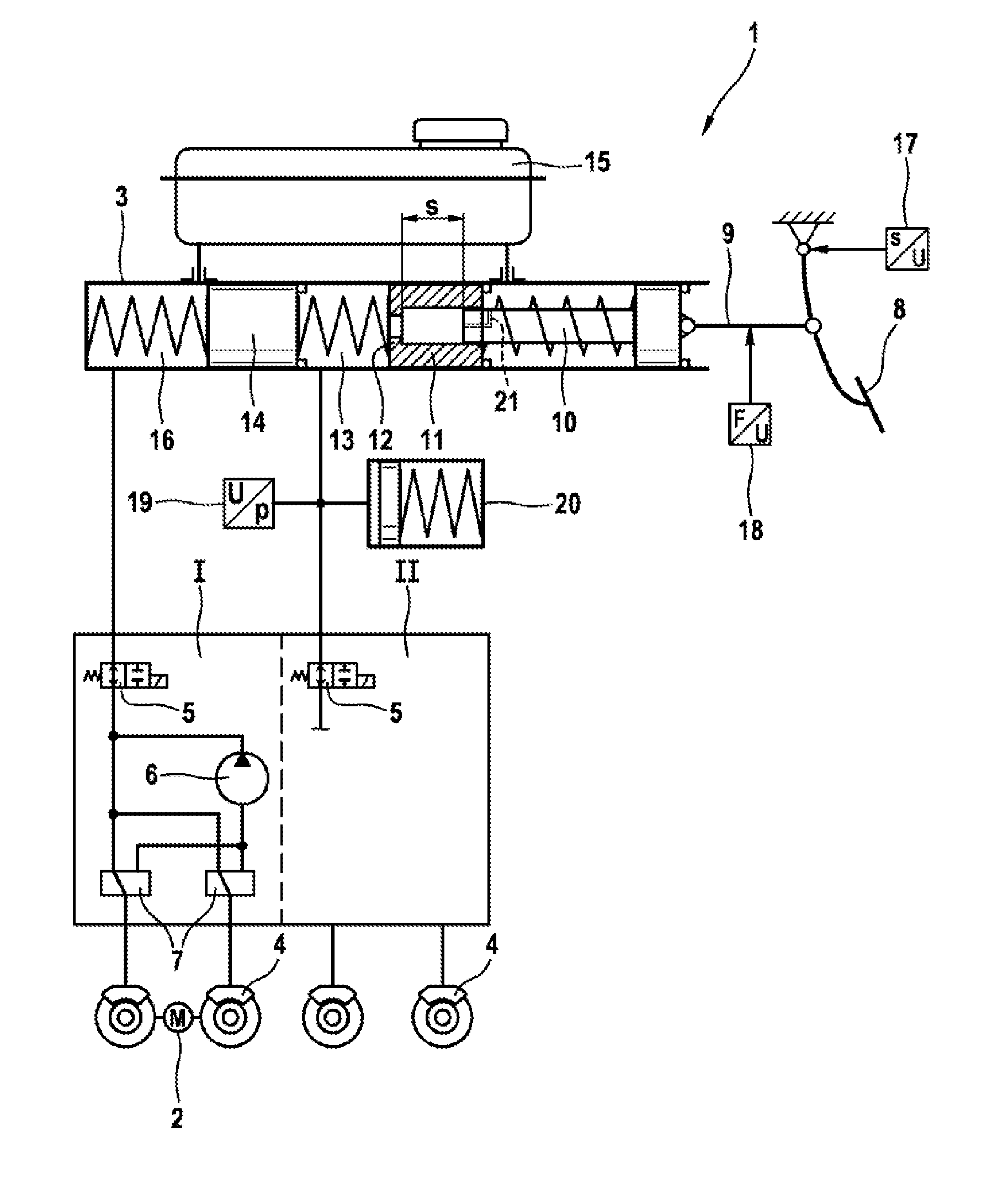
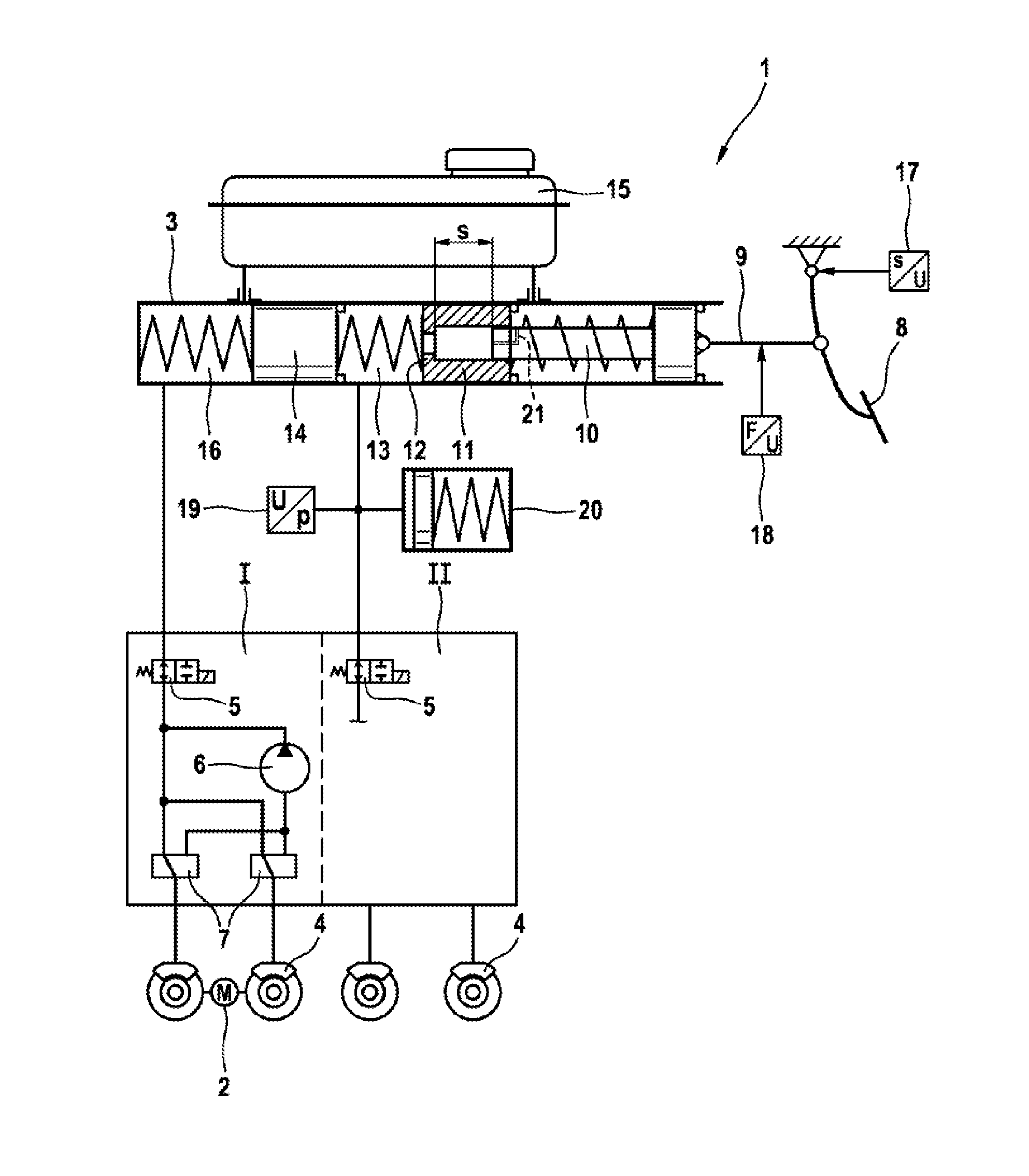
[0023]The hydraulic vehicle brake system 1 according to the invention shown in the drawing is provided for a hybrid vehicle (not shown) i.e. a motor vehicle with an internal combustion engine and an electric motor 2 as drive motors. The electric motor 2 acts on two wheels of a vehicle axle. Several electric motors can for example also be provided for individual or all vehicle wheels (not shown). The vehicle can also be a purely electric vehicle with propulsion by the electric motor 2 without an internal combustion engine. On braking the electric motor 2, generally described as an electric machine 2 and referred to as such below, is operated as a generator to generate electric power which is stored in an accumulator (not shown) and available for propulsion of the motor vehicle with the electric machine 2.

[0024]The vehicle brake system 1 is a dual-circuit vehicle brake system 1 with two brake circuits I, II which are connected to a tandem master brake cylinder 3. Connected to both bra...


PUM


Abstract

A main brake cylinder for a hydraulic vehicle brake system of a motor vehicle is disclosed. The main brake cylinder includes an electric motor that is operated as a generator for decelerating the motor vehicle. For service braking, pressure is applied to a brake circuit by the main brake cylinder and to another brake circuit by a hydraulic pump. In order to reduce a pedal force, a first piston has a smaller piston surface and a second piston only moves if a greater brake fluid volume is required. A preloaded hydraulic accumulator limits an increase in pressure.

Description

[0001]The invention concerns a master brake cylinder for a hydraulic vehicle brake system with the features of the preamble of claim 1, and a method for its operation with the features of the preamble of claim 5.PRIOR ART[0002]Hybrid vehicles are known which have an internal combustion engine and one (or more) electric motor(s) for their propulsion. To decelerate such motor vehicles, the electric motor can be operated as a generator and the current generated stored in an accumulator. Decelerating the motor vehicle with the electric motor operated as a generator is called recuperative braking. The electric motor can generally be regarded as an electric machine, for example it can also be a generator.[0003]To achieve a specific deceleration, a braking effect of the hydraulic vehicle brake system must be reduced by the deceleration effect of the electric machine operated as a generator. In simple systems, a vehicle driver must compensate for the braking effect of the electric machine o...

Claims


Application Information

Patent Timeline
Patent Type & Authority Applications(United States)
IPC IPC(8): B60T13/58B60T13/74
CPCB60T7/042B60T13/165B60T8/4081B60T8/38
Inventor KUNZ, MICHAEL
Owner ROBERT BOSCH GMBH
Why Eureka
Try Eureka