
Method for Identifying Materials Using Dielectric Properties through Active Millimeter Wave Illumination

Active Publication Date: 2012-10-11
US DEPT OF HOMELAND SECURITY
View PDF3 Cites 26 Cited by
  • Summary
  • Abstract
  • Description
  • Claims
  • Application Information

AI Technical Summary

Benefits of technology

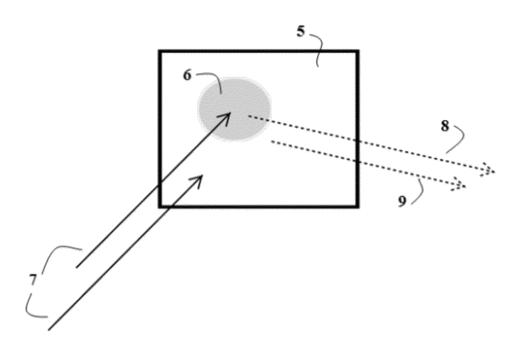
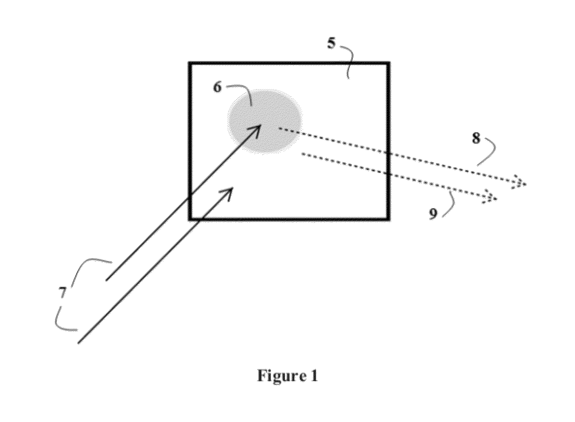
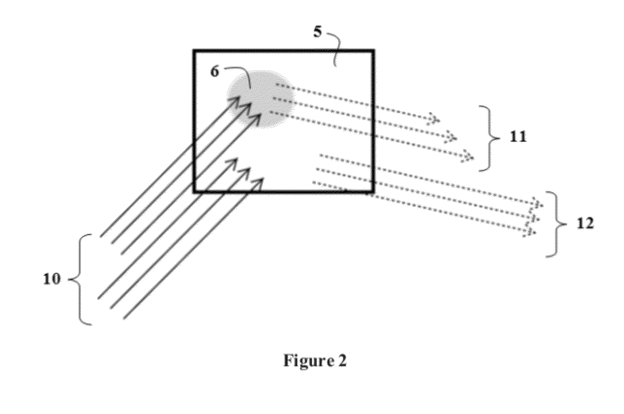
[0005]The disclosed system and method include an active millimeter wave imaging system capable of irradiation by a plurality of frequencies (emitter). Such a system will typically consist of one or more millimeter wave energy sources with a frequency capability between 5 and 500 GHz (gigahertz), a detector for receipt of millimeter wave energy reflected from target zone, a computer or other data processing means and a local or remotely accessible database. Any number of narrower sub-bands between 5 and 500 GHz can be used in the invention. Because the absorption of millimeter wave radiation is frequency dependent, by directing a plurality of millimeter wave radiation emission frequencies through homogeneous target material of different optical depths and calculating the intensity of reflection for each illumination frequency, a linear correlation between the reflected intensity and optical d

Problems solved by technology

Because the detection of objects using millimeter wavelengths relies on the contrast between the millimeter wave reflection intensity from a body and the millimeter wave reflection intensity from an adjoining object or anomaly; the system cannot distinguish between benign objects and contraband.
Such contrast based systems are not geared toward making composition based determinations other than metallic vs. opaque (with shape, or structural based determination methods also known in the prior art).
The inability to determine composition reduces detection to anomaly based detection instead of identity based detection, thus the detection of anomalies such as keys or other benign objects lead to a significant rate of false alarms which is problematic in implementing these systems as a personnel screening tool.

Method used


Image

  • Method for Identifying Materials Using Dielectric Properties through Active Millimeter Wave Illumination
  • Method for Identifying Materials Using Dielectric Properties through Active Millimeter Wave Illumination
  • Method for Identifying Materials Using Dielectric Properties through Active Millimeter Wave Illumination

Examples


Embodiment Construction

[0014]One embodiment of the described invention comprises a millimeter wave energy source capable of emitting (an emitter) at least three different discrete bands of millimeter wave radiation utilizing a frequency range between 5 and 500 GHz, used to illuminate a target zone. Frequencies higher than 500 GHz suffer from high specular reflection from cloth, and make penetration at other than normal angles difficult. A detector, capable of measuring the intensity of reflection received from the target zone is part of the embodiment. A computer or other computational means for receiving and determining the measurement of reflection intensity received from illuminated objects within the target zone that is capable of optimization of the dielectric constant using geometric optics modeling. A database comprising the dielectric properties of materials which is used by the computer means to compare / identify the composition of the target anomaly. Such comparison may be made by computer algori...


PUM


Abstract

Described herein is a method by which active millimeter wave radiation may be used to detect and identify the composition of concealed metallic, concealed non-metallic, concealed opaque or concealed semi-transparent materials based on their optical properties. By actively radiating a semi-transparent target anomaly with multiple millimeter wave radiation frequencies, the dielectric properties of the target anomaly can be identified. The dielectric properties of the target anomaly may then be compared to a library of dielectric properties attributed to semi-transparent materials of interest. This method will allow active millimeter wave radiation technology to identify the likely composition of targeted semi-transparent materials through absorption and illumination measurements attributed to the dielectric properties of the targeted composition.

Description

RELATED APPLICATIONS[0001]This application claims priority under 35 U.S.C. §119(e) to U.S. Provisional Application Ser. No. 61 / 472,926, entitled “Method for Identifying Materials Using Dielectric Properties through Active Millimeter Wave Illumination,” filed on Apr. 7, 2011.BACKGROUND OF INVENTION[0002]Active millimeter wave imaging is useful in security screening for concealed threats because of the property of millimeter waves to penetrate clothing. The technique is employed in personnel screening systems to detect concealed explosives, narcotics, weapons and other contraband in or beneath an individual's clothing because of the noninvasive nature of the scanning method and lack of physical contact required during an inspection. The detection method relies on the identification of anomalies in the images produced by the reflected radiation returned from the body of an inspected subject.[0003]Millimeter wavelengths are relatively long and inherently lower in resolution than images ...

Claims


Application Information

Patent Timeline
IPC IPC(8): G01S13/89
CPCG01S7/412G01S13/89G01S13/887
Inventor SMITH, BARRY THOMASWEATHERALL, JAMES CHRISTOPHERBARBER, JEFFREY BRIAN
Owner US DEPT OF HOMELAND SECURITY
Learn More