Monolithic ceramic capacitor
a ceramic capacitor and monolithic technology, applied in the direction of fixed capacitors, stacked capacitors, fixed capacitor details, etc., can solve the problems of increased manufacturing cost, prone to occur, prolonged manufacturing time, etc., and achieve the effect of reducing the thickness of the ceramic layer, and increasing the polarization of the ceramic layer in the first portion
- Summary
- Abstract
- Description
- Claims
- Application Information
AI Technical Summary
Benefits of technology
Problems solved by technology
Method used
Image
Examples
first preferred embodiment
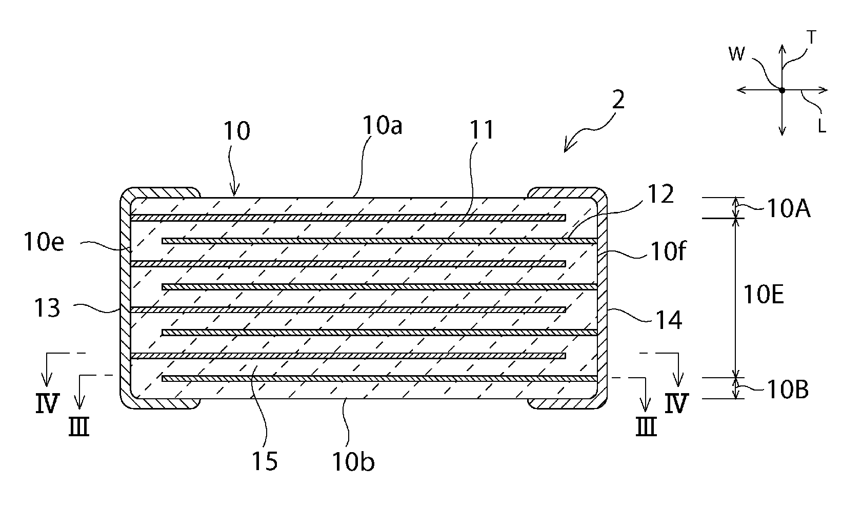
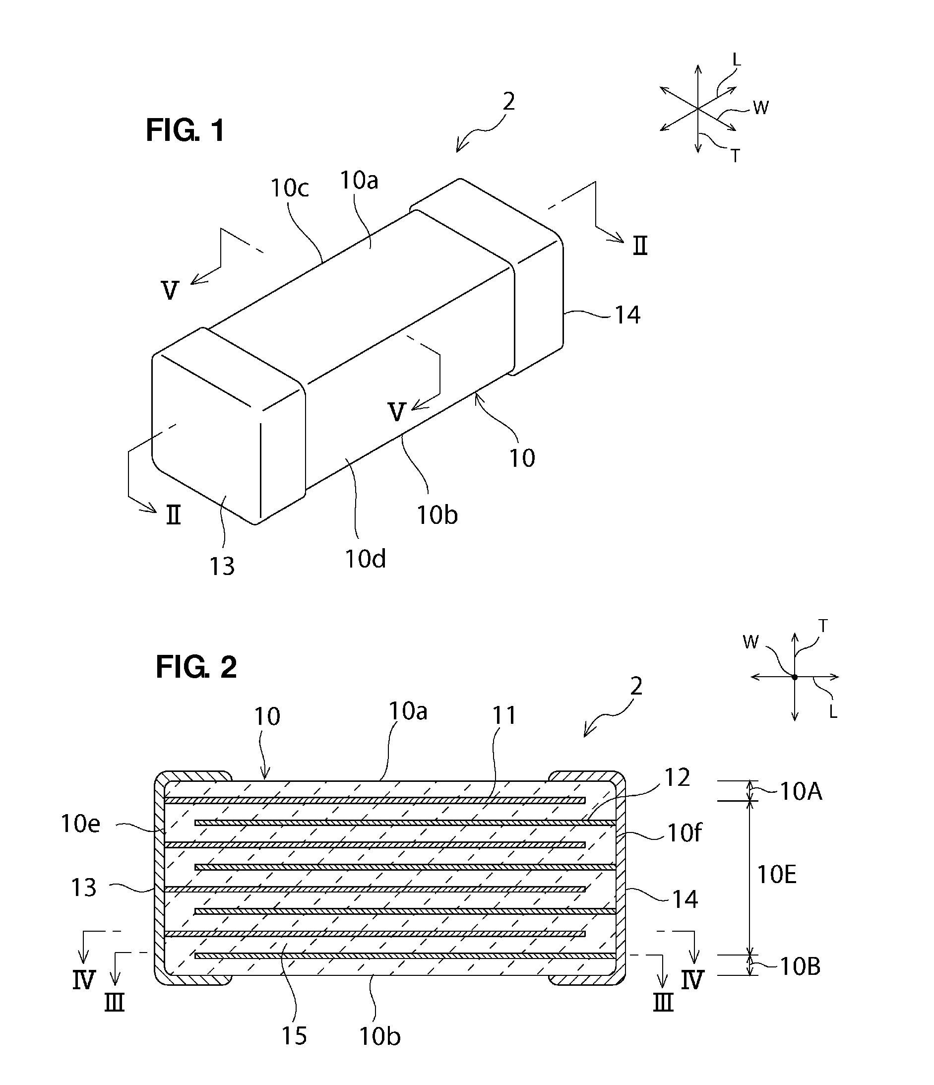
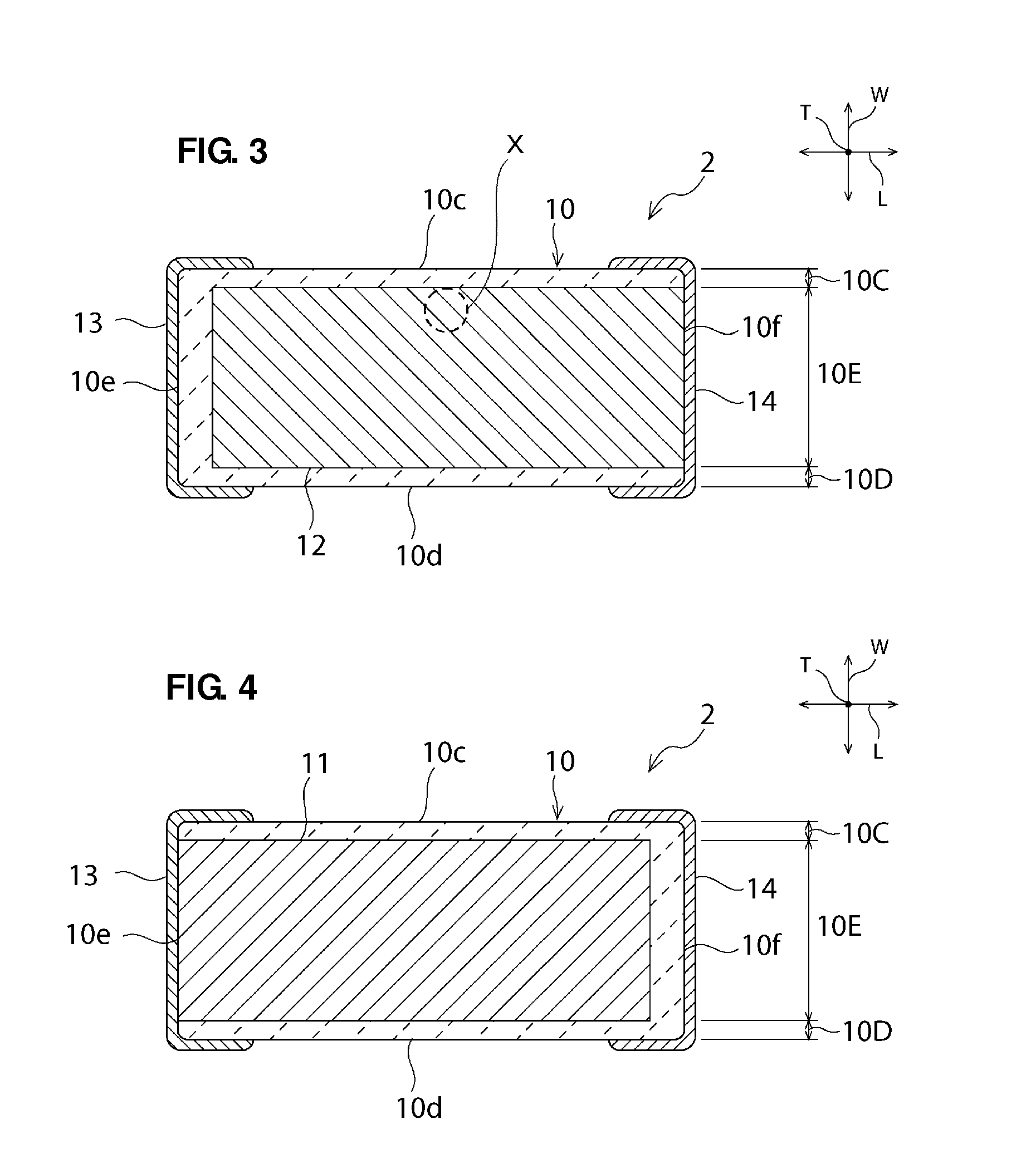
[0028]FIG. 1 is a schematic perspective view of a ceramic capacitor according to a first preferred embodiment of the present invention. FIG. 2 is a schematic sectional view taken along a line II-II in FIG. 1. FIG. 3 is a schematic sectional view taken along a line III-III in FIG. 2. FIG. 4 is a schematic sectional view taken along a line IV-IV in FIG. 2.
[0029]A monolithic ceramic capacitor 2 according to the present preferred embodiment includes a ceramic sintered body 10 having a parallelepiped shape. The ceramic sintered body 10 includes first and second principal surfaces 10a and 10b, first and second lateral surfaces 10c and 10d, and first and second end surfaces 10e and 10f. The first and second principal surfaces 10a and 10b extend in a lengthwise direction L and a widthwise direction W. The first and second lateral surfaces 10c and 10d extend in the lengthwise direction L and a thickness direction T. The first and second end surfaces 10e and 10f extend in the widthwise direct...
second preferred embodiment
[0057]The present invention is not limited to the above-described monolithic ceramic capacitor according to the first preferred embodiment, and the present invention can provide monolithic ceramic capacitors of various structures. FIG. 9 is a schematic perspective view of a ceramic capacitor according to a second preferred embodiment of the present invention. FIG. 10 is a sectional view of a portion taken along a line II-II in FIG. 9, FIG. 11 is a sectional view taken along a line III-III in FIG. 9, and FIG. 12 is a sectional view taken along a line IV-IV in FIG. 9.
[0058]As illustrated in FIG. 9, a monolithic ceramic capacitor 101 according to the present preferred embodiment includes a ceramic sintered body 10 preferably having a parallelepiped shape. The ceramic sintered body 10 includes first and second principal surfaces 10a and 10b, first and second lateral surfaces 10c and 10d, and first and second end surfaces 10e and 10f. The first and second principal surfaces 10a and 10b e...
examples
[0078]The monolithic ceramic capacitor according to the first preferred embodiment, illustrated in FIG. 1, was fabricated by the above-described manufacturing method in accordance with non-limiting examples of design parameters mentioned below.
[0079]Composition of the ceramic layer 15: BaTiO3
[0080]Layer thickness of the ceramic layer 15: 0.8 μm
[0081]Dimensions of the ceramic sintered body: 1.0 mm×0.5 mm×0.5 mm (tolerance±0.1 mm)
[0082]Thickness of the outer layer (on one side): 36 μm
[0083]Material of the inner electrode: Ni
[0084]Thickness of the inner electrode: 0.5 μm
[0085]Layer number of the inner electrodes: 380 layers
[0086]Firing temperature: 1200° C.
[0087]Material of the outer electrode: Cu (including Ni and Sn plated thereon)
[0088]Baking temperature for the outer electrode: 800° C.
[0089]Further, Samples 1 to 8 of the monolithic ceramic capacitor 2 were fabricated by variously setting the sizes of the side gap portions 10C and 10D in the widthwise direction, the size of the not...
PUM
| Property | Measurement | Unit |
|---|---|---|
| length | aaaaa | aaaaa |
| length | aaaaa | aaaaa |
| length | aaaaa | aaaaa |
Abstract
Description
Claims
Application Information
 - R&D
- Intellectual Property
- Life Sciences
- Materials
- Tech Scout
- Unparalleled Data Quality
- Higher Quality Content
- 60% Fewer Hallucinations
Browse by: Latest US Patents, China's latest patents, Technical Efficacy Thesaurus, Application Domain, Technology Topic, Popular Technical Reports.
© 2025 PatSnap. All rights reserved.Legal|Privacy policy|Modern Slavery Act Transparency Statement|Sitemap|About US| Contact US: help@patsnap.com


