
Method and controller for generating a blade pitch angle control signal and wind turbine comprising the controller

a technology of control signal and blade, which is applied in the direction of rotors, marine propulsion, vessel construction, etc., can solve the problems of reducing the power production and thus efficiency of the wind turbine, excessive vibration of the wind turbine blade, and excessive vibration in the supporting structures, so as to reduce the damage of mechanical components of the blade or the wind turbine, the method may be simplified, and the effect of avoiding damag

Inactive Publication Date: 2012-10-11
SIEMENS AG
View PDF3 Cites 33 Cited by
  • Summary
  • Abstract
  • Description
  • Claims
  • Application Information

AI Technical Summary

Benefits of technology

[0013]Generating the blade pitch angle control signal such that it varies in accordance with the rotor blade vibration motion, in particular an edgewise rotor blade vibration motion, may enable to vary the blade pitch angle in accordance (in particular synchronously) with the rotor blade vibration motion. Thereby, an effective damping of the rotor blade vibration motion may be achieved.
[0019]Thus, in particular during the first portion of the rotor blade vibration repetition period the leading edge or upstream edge of the rotor blade is moved away from the wind and during the second portion of the rotor blade vibration repetition period the leading edge or upstream edge of the rotor blade is moved towards the wind. Thereby, an effective aerodynamic damping of the rotor blade vibration motion may be achieved.
[0028]According to an embodiment, the blade pitch angle control signal is generated such as to cause varying the blade pitch angle, when the rotor blade vibration motion has an amplitude exceeding a threshold, wherein the blade pitch angle control signal is generated such as to cause maintaining the blade pitch angle at a nominal blade pitch angle, when the rotor blade vibration motion has an amplitude being lower than or equal to the threshold. In particular, according to an embodiment, the threshold of the rotor blade vibration motion may be exceeded only during 1%-5% of an operation time of the wind turbine. Thus, the damping method may not continuously be applied, but may be applied only during certain time intervals, in which the amplitude of the rotor blade vibration motion exceeds the threshold. Thereby, the method may be simplified and negative effects due to the varying the blade pitch angle may be avoided.
[0030]In particular, the nacelle or the wind turbine may comprise one or more acceleration sensors for sensing accelerations of the wind turbine, in particular the nacelle, along one or more directions, in particular along a horizontal direction for sensing side by side movements of the turbine, in particular the nacelle. In particular, it may not be required to determine the rotor blade vibration motion based on a signal generated by an acceleration sensor mounted at the rotor blade. Thereby, costs for determining the rotor blade vibration motion may be reduced.
[0033]According to an embodiment of the present invention, the generating the blade pitch angle control signal comprises at least one of the following signal processing steps in series (or / and in parallel) on the modulated wind turbine vibration signal: band pass filtering (including removing signals having a frequency above or below certain thresholds); delaying (in particular comprising adding a time offset); amplifying (in particular comprising increasing, decreasing the signal such as to satisfy particular conditions, such as to fall within a predetermined range); restricting a change rate (such that the change rate, i.e. an amount of change with time, being within a particular range of a change rate); restricting a magnitude (such that the resulting signal lies within a predetermined range); adding to a nominal blade pitch angle signal (wherein the nominal blade pitch angle signal may be a normal blade pitch angle signal which is determined based on the wind condition and / or energy production state); and supplying to an actuator (arranged for turning the rotor blade around its longitudinal axis) configured for changing the blade pitch angle. Thereby, damage of mechanical components of the blade or the wind turbine may be reduced or even avoided.
[0034]According to an embodiment of the present invention, the wind turbine vibration signal is measured using an accelerometer, in particular mounted at a nacelle supporting a rotor shaft at which the rotor blade is connected. In particular, the accelerator may be configured to measure or sense an acceleration of the nacelle, in particular an acceleration in a horizontal direction such as to sense a side-side vibration of the nacelle. Thereby, the method may be simplified and may not require expensive equipment.

Problems solved by technology

In particular, under high loads and / or in high turbulence, in near wake, or with blade icing, a wind turbine blade may vibrate excessively, in particular in an edgewise direction which may lie at least approximately in a plane corresponding to the rotor plane being perpendicular to a rotor shaft at which the rotor blade is fixed.
The oscillation of the rotor blade or the vibration of the rotor blade, in particular in the edgewise direction, may cause excessive vibration in the supporting structures, such as for example a bearing which supports the rotor shaft or other supporting or holding components.
However, while protecting the blade from damages, this approach may reduce the power production and thus efficiency of the wind turbine.
However, it has been observed that the conventional methods and arrangement for damping a rotor blade vibration are not effective enough or may require expensive and difficulty to manufactured components.

Method used


Image

  • Method and controller for generating a blade pitch angle control signal and wind turbine comprising the controller
  • Method and controller for generating a blade pitch angle control signal and wind turbine comprising the controller
  • Method and controller for generating a blade pitch angle control signal and wind turbine comprising the controller

Examples


Embodiment Construction

[0048]The illustration in the drawings is in schematic form.

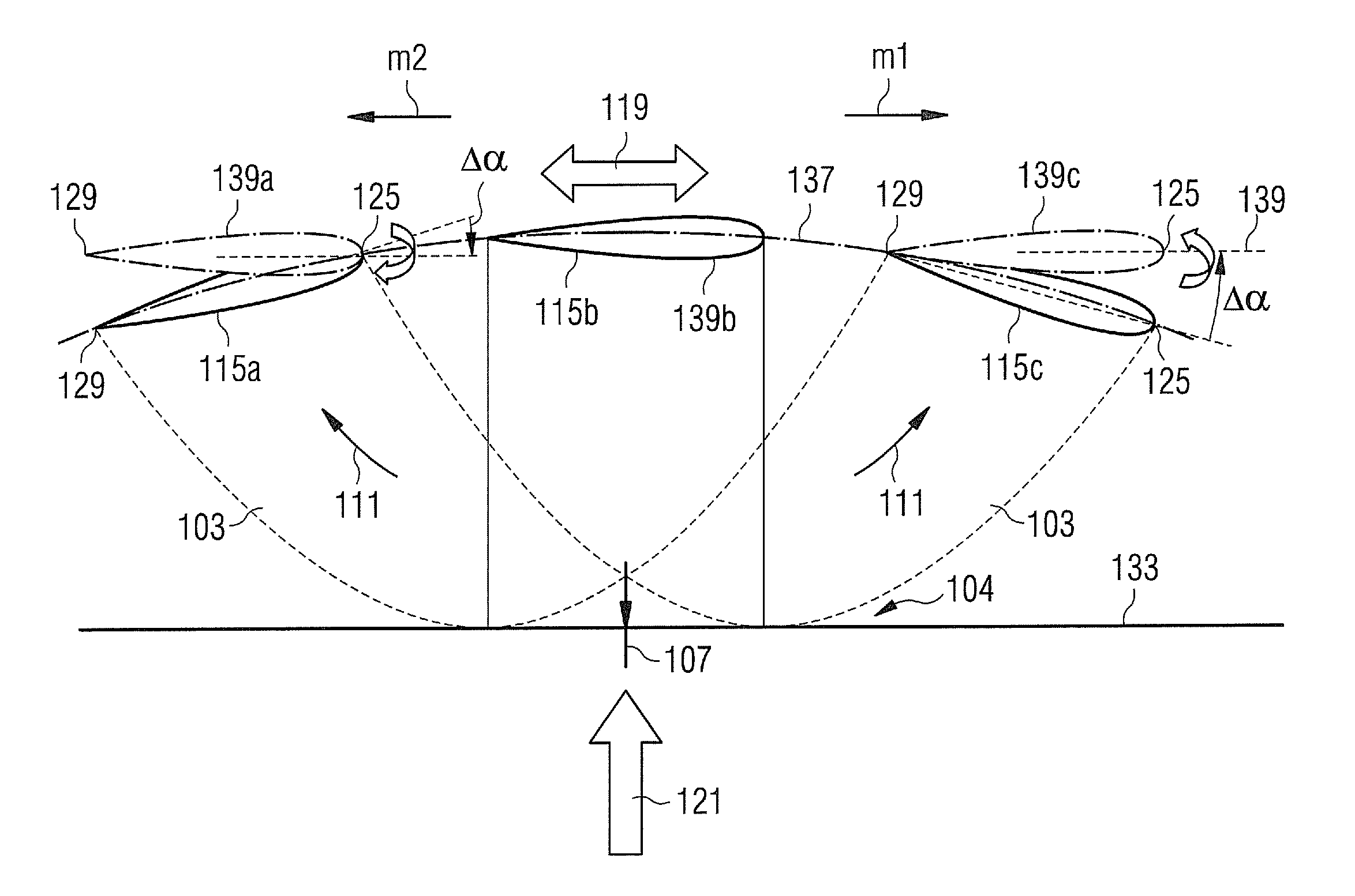
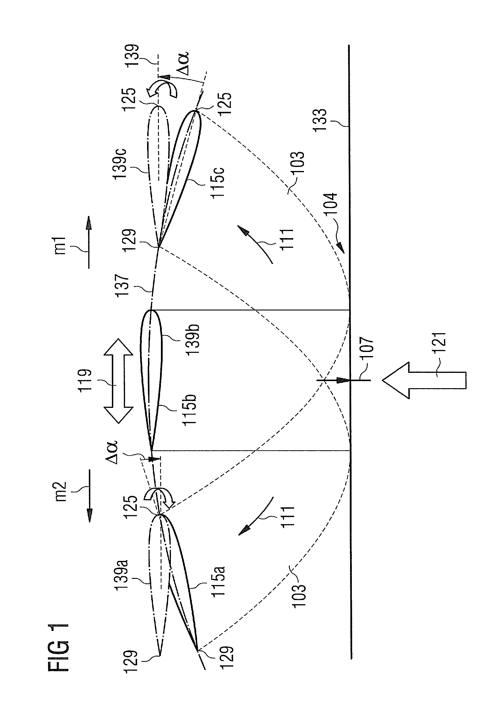
[0049]FIG. 1 schematically illustrates a method for varying a blade pitch angle according to an embodiment of the present invention. In particular, FIG. 1 illustrates damping of a rotor blade edgewise motion in a high load condition of an operating wind turbine.

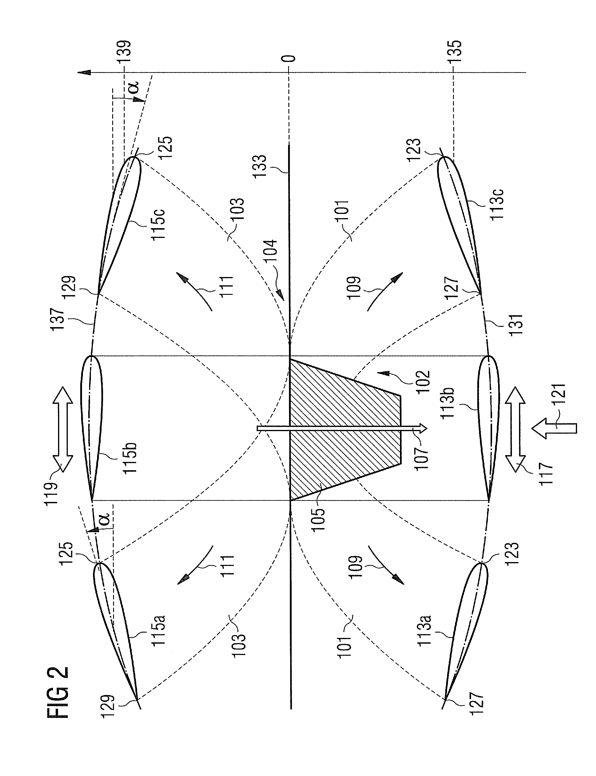
[0050]An undamped edgewise motion of the rotor blade is schematically illustrated in FIG. 2 for a low load condition as well as for a high load condition. In FIG. 2 a single rotor blade 101, 103 is illustrated as viewed approximately along its longitudinal axis, wherein the rotor blade 101 represents a situation during a low load condition, while the rotor blade 103 represents a situation during a high load condition.

[0051]At a radially inner portion 102, 104 the rotor blade 101, 103 is connected to a rotor hub 105 which rotates around a rotation axis 107. The rotor hub 105 may be connected to a rotor shaft. In particular, the rotor hub or the rotor shaft may be rota...


PUM


Abstract

A method for generating a blade pitch angle control signal for controlling a blade pitch angle of a rotating rotor blade for damping a rotor blade vibration, in particular an edgewise rotor blade vibration, of the rotating rotor blade is disclosed. The blade pitch angle control signal is generated such that it varies in accordance with a rotor blade vibration motion. A controller and a wind turbine are also disclosed.

Description

FIELD OF INVENTION[0001]The present invention relates to a method and to a controller for generating a blade pitch angle control signal for controlling a blade pitch angle of a rotating rotor blade for damping a rotor blade vibration, in particular an edgewise rotor blade vibration, of the rotating rotor blade, wherein the rotor blade is in particular comprised in a wind turbine.ART BACKGROUND[0002]During rotation of a rotor blade of a wind turbine, the rotor blade may oscillate according to one or more oscillation modes. In particular, under high loads and / or in high turbulence, in near wake, or with blade icing, a wind turbine blade may vibrate excessively, in particular in an edgewise direction which may lie at least approximately in a plane corresponding to the rotor plane being perpendicular to a rotor shaft at which the rotor blade is fixed. The oscillation of the rotor blade or the vibration of the rotor blade, in particular in the edgewise direction, may cause excessive vibr...

Claims


Application Information

Patent Timeline
IPC IPC(8): F03D7/04F03D7/00
CPCF03D7/0224Y02E10/723F03D7/0296Y02E10/72
Inventor EGEDAL, PERNGUYEN, KHANH
Owner SIEMENS AG
Learn More