
Hydraulic System for Construction Machinery

a technology for construction machinery and hydraulic systems, applied in the direction of functional valve types, servomotors, transportation and packaging, etc., can solve the problems of difficult steering wheel control and much effort required to control the steering wheel, and achieve the effect of easy steering wheel control

Active Publication Date: 2012-10-18
DOOSAN INFRACORE CO LTD
View PDF3 Cites 3 Cited by
  • Summary
  • Abstract
  • Description
  • Claims
  • Application Information

AI Technical Summary

Benefits of technology

[0008]Accordingly, the present disclosure has been made in an effort to provide a hydraulic system for construction machinery that can make steering wheel control easy even when engine rpm is in a low range.
[0016]According to the present disclosure, by supplementing the flow to the steering unit through operating an auxiliary pump when the flow to the steering unit is deficient, the steering wheel may be prevented from becoming heavy, even when engine rpm is in a low range, to thereby improve controllability of the steering wheel.
[0017]Also, by stopping the operating of the auxiliary pump when it is determined that the flow supplied to the steering unit is excessive, energy loss may be minimized.

Problems solved by technology

As a result, much effort is required to control the steering wheel, causing much difficulty in controlling the steering wheel.

Method used


Image

  • Hydraulic System for Construction Machinery
  • Hydraulic System for Construction Machinery
  • Hydraulic System for Construction Machinery

Examples


Embodiment Construction

[0023]Hereinafter, a hydraulic system for construction machinery according to an exemplary embodiment of the present disclosure will be described in detail.

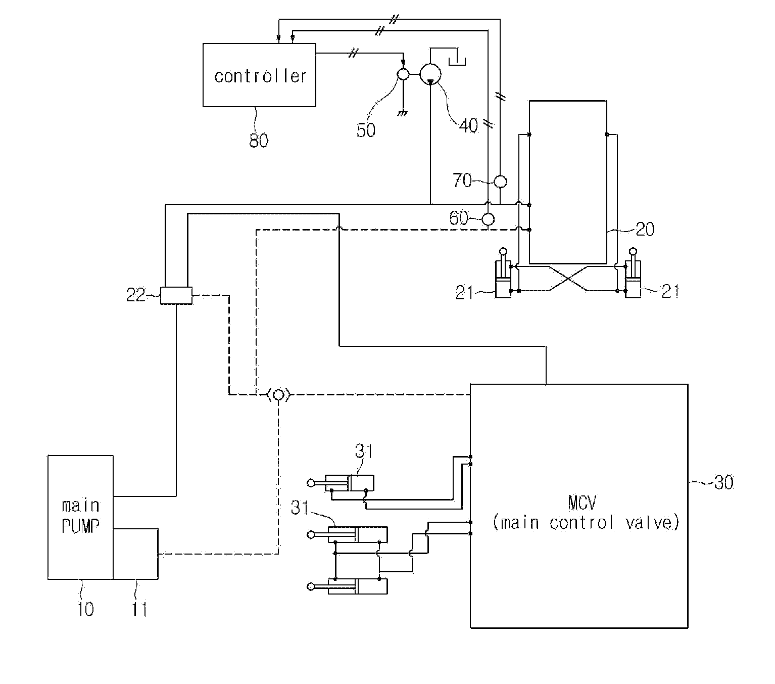
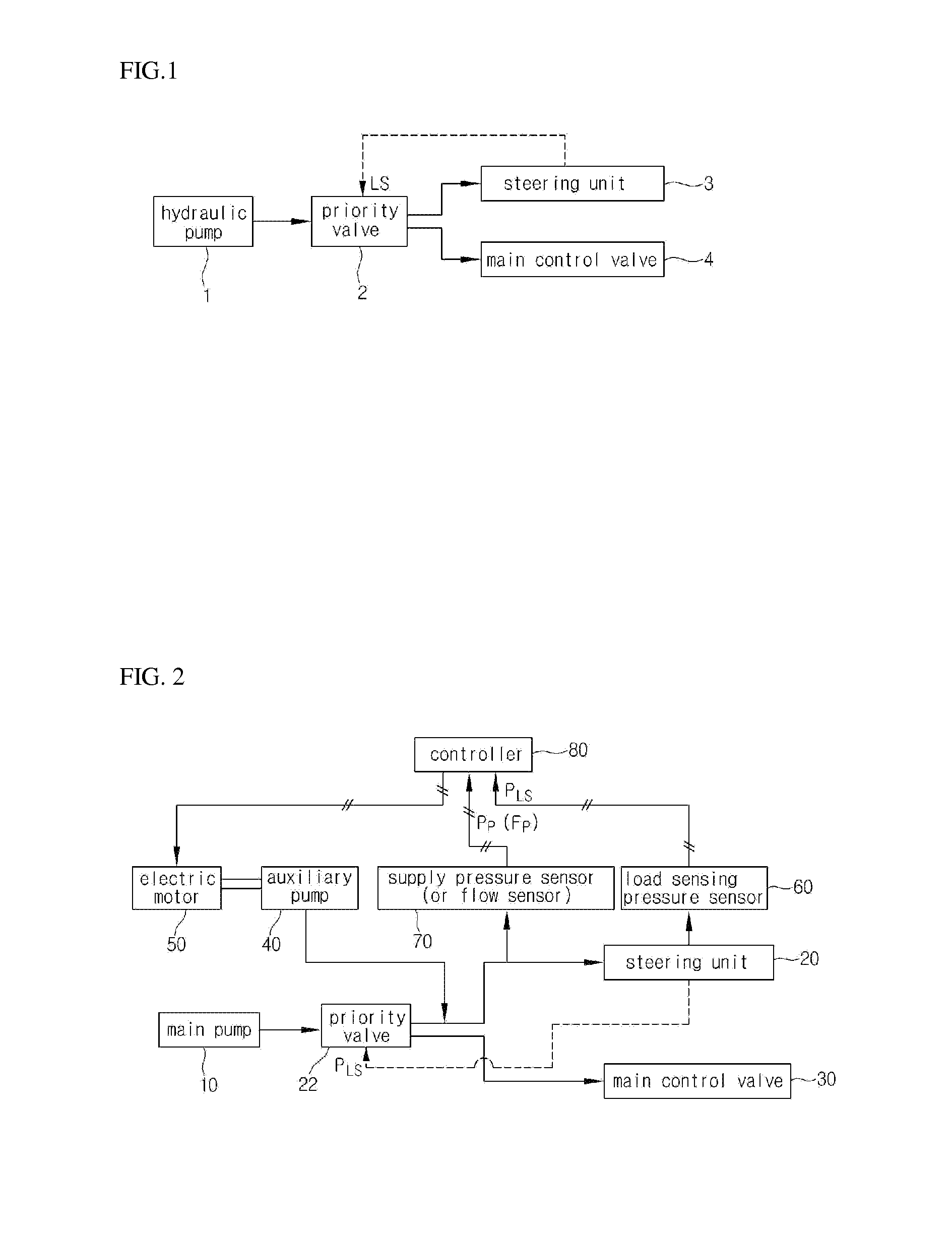
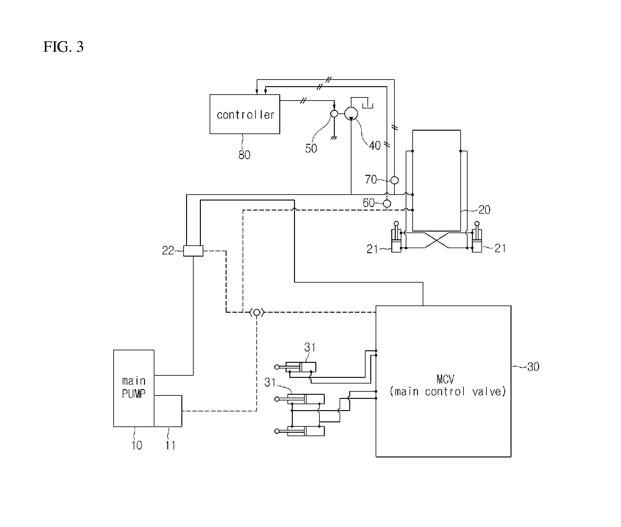
[0024]Referring to FIG. 2, a hydraulic system for construction machinery according to an exemplary embodiment of the present disclosure is applied to construction machinery in which working fluid discharged from a main pump 10 is simultaneously supplied to a steering unit 20 and a main control valve 30, and which includes an auxiliary pump 40, an electric motor 50, a load sensing pressure sensor 60, a supply pressure sensor 70, and a controller 80.

[0025]The auxiliary pump 40 is for supplementing working fluid when the flow of working fluid supplied to the steering unit 20 is deficient, and may have a smaller capacity than the main pump 10.

[0026]The electric motor 50 is for operating the auxiliary pump 40, and is directly coupled to the auxiliary pump 40. The rpm of the electric motor 50 and whether the electric motor 50 is rotate...


PUM


Abstract

The present disclosure relates to a hydraulic system for construction machinery, which is applied to construction machinery provided with a steering unit for controlling steering of equipment, and a main control valve for controlling operating of a work tool, and includes: a main pump for discharging working fluid supplied to the steering unit and the main control valve; a load sensing pressure sensor for sensing a load sensing pressure of the steering unit; a priority valve installed in a supply passage for the working fluid discharged from the main pump, for dividing and supplying the working fluid discharged from the main pump to the steering unit and the main control valve, to correspond to the load sensing pressure; an auxiliary pump for supplementing working fluid to the supply passage supplying the working fluid divided by the priority valve to the steering unit; an electric motor for operating the auxiliary pump; and a controller for operating the electric motor when the load sensing pressure is greater than a reference load sensing pressure, and additionally supplying working fluid discharged from the auxiliary pump the steering unit.

Description

[0001]This Application is a Section 371 National Stage Application of International Application No. PCT / KR2010 / 007709, filed Nov. 3, 2010 and published, not in English, as WO2011 / 074781 on June 23, 2011.FIELD OF THE DISCLOSURE[0002]The present disclosure relates to construction machinery such as a wheel loader, and particularly, to a hydraulic system for construction machinery that uses working fluid discharged from one hydraulic pump to operate a work tool and a steering unit.BACKGROUND OF THE DISCLOSURE[0003]In general, construction machinery such as a wheel loader uses working fluid discharged from a hydraulic pump connected directly to an engine to operate a steering unit and a work tool. In particular, hydraulic systems that supply working fluid discharged from one hydraulic pump simultaneously to a steering unit and a work tool are currently in use. In such hydraulic systems, working fluid supplied to a steering unit and a work tool should be efficiently distributed, and an ex...

Claims


Application Information

Patent Timeline
Patent Type & Authority Applications(United States)
IPC IPC(8): F16K21/04
CPCE02F9/2242B62D5/065B62D5/07E02F9/207E02F9/2087E02F9/225F15B11/162F15B2211/20515F15B2211/20523F15B2211/20576F15B2211/2658F15B2211/6309F15B2211/6313Y10T137/86002
Inventor KIM, JEUNG HWA
Owner DOOSAN INFRACORE CO LTD
Learn More