
Coil electrical component and method of manufacturing the same

a technology of electrical components and coils, applied in the field of coil electrical components, can solve the problems of inability to use any shape of molds, inability to meet the uniformity of magnetic field lines and low saturation current, and increase the manpower and time cost of winding coils, so as to improve the quality of inductor and reduce production costs

Active Publication Date: 2012-10-18
MAGIC TECH
View PDF4 Cites 15 Cited by
  • Summary
  • Abstract
  • Description
  • Claims
  • Application Information

AI Technical Summary

Benefits of technology

[0008]In view of the mentioned disadvantages of the prior techniques, an object of the present invention is to provide a coil electrical component and a method of manufacturing the coil electrical component, in order to economize production cost and improve quality of the inductor.

Problems solved by technology

Although the ring inductor used in the power supply equipment do not need to consider the volume issue, the manpower and time cost for winding the coil are also relatively increased.
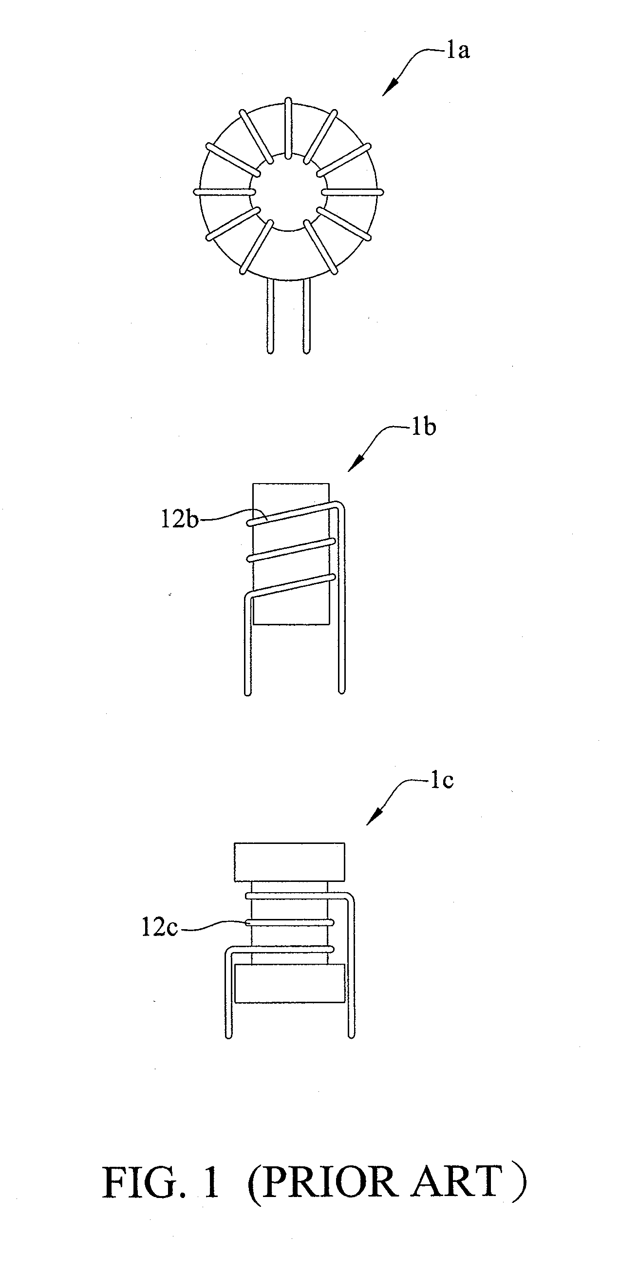
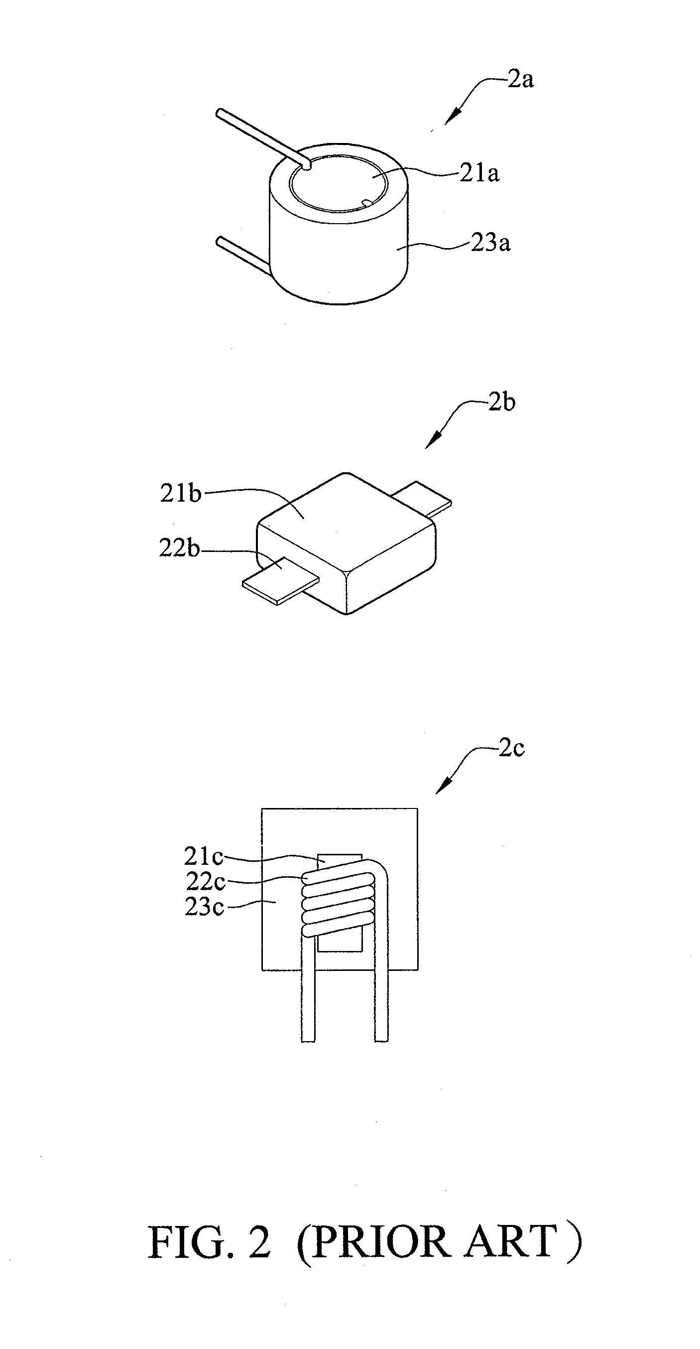
However, the magnetic field lines of the aforementioned three inductors are exposed to the air and which results to non-uniform in magnetic field lines and low saturation current.
However, such technique cannot be used in any shape of mold.
In addition, the large scale inductor as an example, it is not easy to reduce the production cost, since an extremely large pressure is needed to provide the mechanism exerting pressure on the inductor for molding.
It is difficult to achieve a vacuum state during the process, besides, owing to the specific gravity of the magnetic powder is greater than the gel, thus settlement phenomena may occur in the gel.
These problems or phenomena may often affect the characteristics of the inductors.

Method used


Image

  • Coil electrical component and method of manufacturing the same
  • Coil electrical component and method of manufacturing the same
  • Coil electrical component and method of manufacturing the same

Examples


Embodiment Construction

[0021]The following illustrative embodiments are provided to illustrate the disclosure of the present invention, these and other advantages and effects can be apparently understood by those in the art after reading the disclosure of this specification. The present invention can also be performed or applied by other different embodiments. The details of the specification may be on the basis of different points and applications, and numerous modifications and variations can be devised without departing from the spirit of the present invention.

[0022]Furthermore, the invention of the instructions are simplified schematic diagram, the only way to indicate that the basic technical idea of the invention, so the actual implementation of each component type, quantity and proportion of visual implementation of the requirements change.

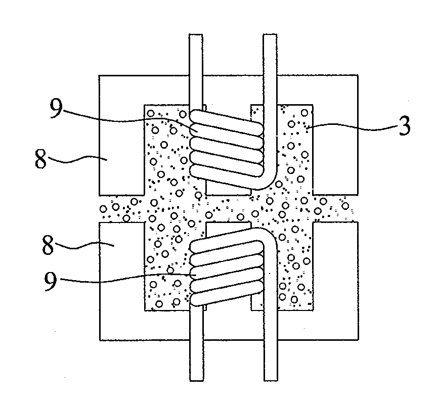
[0023]Referring to FIG. 3A and FIG. 3B, FIG. 3A shows a schematic flow chart of a non-high pressure solid-state packaging method of manufacturing a coil electric...


PUM

PropertyMeasurementUnit
Weightaaaaaaaaaa
Shapeaaaaaaaaaa
Soft magnetismaaaaaaaaaa

Abstract

A coil electrical component and a method of manufacturing the same. Magnetic material powder and adhesive powder are mixed in a predetermined proportion to form a solid mixture. The solid mixture and an object, such as a coil or a core material surrounded by the coil, are filled in a mold having a predetermined shape. The solid mixture in the mold is heated such that the magnetic material powder is adhered by the adhesive powder and covers the object, so as to form the coil electrical component. The coil electrical component corresponds in shape to the mold. Therefore, the coil electrical component has stable quality, and can be manufactured with less time and lower cost.

Description

BACKGROUND OF THE INVENTION[0001]1. Field of the Invention[0002]The present invention relates generally to an electrical component and a method of manufacturing the same, and, more particularly, to a coil electrical component and a method of manufacturing the same.[0003]2. Description of Prior Art[0004]A coil electrical component is usually designed to resist change of the current. For example, when the current flows through the inductor, a magnetic field is produced. Change of the magnetic field may induce change of the voltage and resist change of the current. The ability to inhibit the current change is called inductance.[0005]In general, the early common inductor is ring inductor 1a having functions of self-shielding, high coupling and premature saturation, as shown in FIG. 1. In recent years, the demand for the inductor mounted on the circuit board is the trend of miniaturization, however, while the ring inductor 1a is larger in volume. Although the ring inductor used in the po...

Claims


Application Information

Patent Timeline
IPC IPC(8): H01F27/02H01F41/00
CPCH01F27/022H01F27/255Y10T29/4902H01F2017/048H01F41/026
Inventor LO, PENG-CHENTAN, LUNG CHING
Owner MAGIC TECH
Learn More