
High gain low profile multi-band antenna for wireless communications

a multi-band antenna, high gain technology, applied in the direction of antenna details, slot antennas, antennas, etc., can solve the problem of difficult multi-band antenna design, and achieve the effect of high gain, high efficiency and good return loss

Inactive Publication Date: 2012-10-18
HE ZIMING +1
View PDF8 Cites 14 Cited by
  • Summary
  • Abstract
  • Description
  • Claims
  • Application Information

AI Technical Summary

Benefits of technology

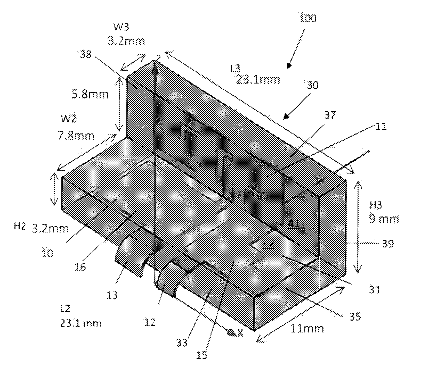
[0007]The primary object of the present invention is to provide a high gain, high efficiency, wideband and low profile multi-band antenna with good return loss for wireless applications such as WLAN Access Point, ZigBee or WiMAX module, notebook computer, tablet computer and other mobile and portable devices applications.
[0008]Aside from performance considerations, another object of the present invention is to provide an antenna that is cost effective so that the antenna can be manufactured and sold at a sufficiently low price for market acceptance.
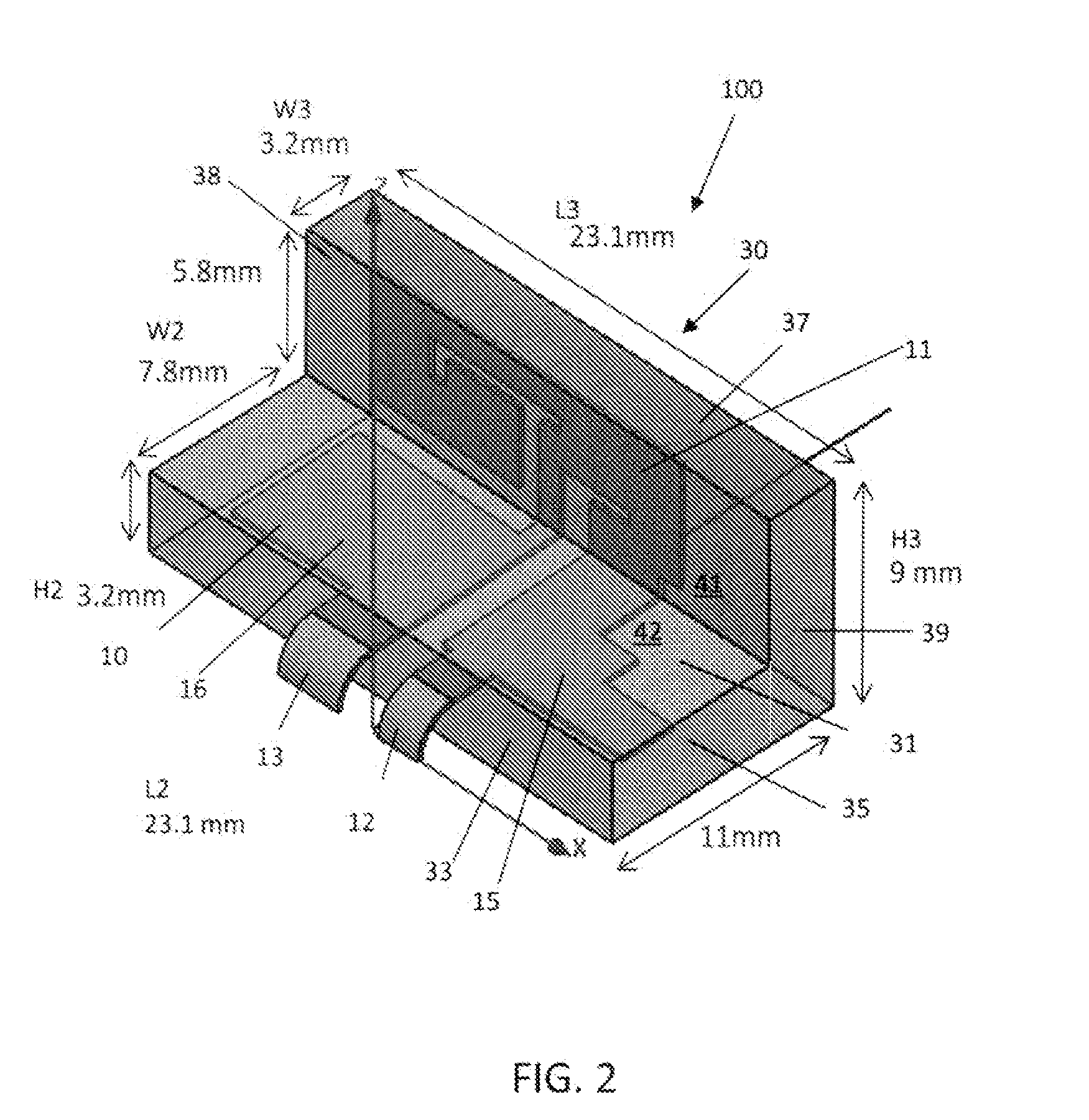
[0009]Another object of the present invention is to provide a low profile antenna that is compact in size especially small in one dimension so it can be easily fabricated and embedded into a notebook computer and tablet computer.

Problems solved by technology

However, in most cases the multi-band antenna design is difficult since it is hard to get enough bandwidth with good return loss for each frequency band (For example, cellular phone antenna often has a −5 dB return loss at the edges of operating frequency band even if matching circuit is applied).

Method used


Image

  • High gain low profile multi-band antenna for wireless communications
  • High gain low profile multi-band antenna for wireless communications
  • High gain low profile multi-band antenna for wireless communications

Examples


Embodiment Construction

[0029]The present invention provides a small, good performance and low cost antenna design. For wireless communication applications, there are generally three challenging requirement for embedded antenna: small size, good performance and low cost. The good performance means that the antenna should have wide bandwidth, good return loss, high gain and high radiation efficiency. To reach the aforementioned goal, Field-Confined Wideband Antenna Technology principle is used in the antenna design of the present invention (See US patent application Publication No. 20110128199, “Field-Confined Wideband Antenna for Radio Frequency Front End Integrated Circuits”, publication date Jun. 2, 2011, the disclosure of which is incorporated herein by reference).

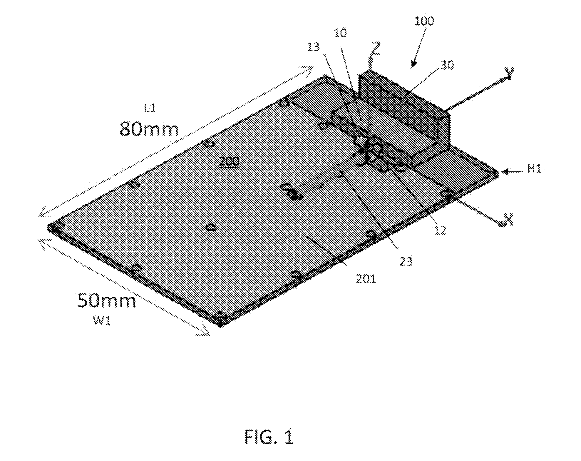
[0030]FIG. 1 shows a perspective view of an embodiment of the antenna assembly 100 mounted onto an exemplary printed circuit board 200. It will be appreciated that, while not otherwise depicted, additional components necessary for wireless com...


PUM


Abstract

The present invention is a low profile, wideband, high gain and high efficiency multi-band antenna with good return loss for wireless applications such as WLAN Access Point, ZigBee or WiMAX module, notebook computer, tablet computer and other mobile and portable devices applications and it can be used with any RF-front end circuitry that is working at 2.4-2.5 GHz, 3.2-3.5 GHz and 4.9-6.8 GHz frequency band. Moreover, the antenna assembly comprises a radiating element and two parasitic branches, all of which are sealed in a plastic housing with the feed pin and ground pin exposed for soldering onto a printed circuit board and thus it is easy for customers to assemble; they just need to solder the antenna pins on a printed circuit board and it will be operational. The L-shaped structure and the plastic housing make the antenna to be compact in size so it can be easily fabricated and employed in computers.

Description

REFERENCE TO RELATED APPLICATIONS[0001]This patent application claims the benefit of U.S. Provisional Application No. 61 / 476,713 filed on Apr. 18, 2011, the disclosure of which is incorporated herein by reference in its entirety.BACKGROUND OF THE INVENTION[0002]1. Field of the Invention[0003]The present invention relates to the architecture of a compact, wideband, high gain and high efficiency tri-band antenna for wireless communications and the antenna can be used with any RF-front end circuitry that is working at 2.4-2.5 GHz, 3.2-3.5 GHz and 4.9-6.8 GHz frequency band.[0004]2. Description of Related Art[0005]Current wireless communication devices such as notebook computer, tablet computer etc. have an increasing demand for wide bandwidth, high gain multi-band antennas. However, in most cases the multi-band antenna design is difficult since it is hard to get enough bandwidth with good return loss for each frequency band (For example, cellular phone antenna often has a −5 dB return ...

Claims


Application Information

Patent Timeline
Patent Type & Authority Applications(United States)
IPC IPC(8): H01Q13/10H01Q5/01H01Q19/00H01Q5/10
CPCH01Q1/243H01Q1/40H01Q5/385H01Q5/371H01Q9/42
Inventor HE, ZIMINGPENG, PING
Owner HE ZIMING
Learn More