Light Guide Element, Backlight Unit, and Display Device

a technology of backlight unit and light guide element, which is applied in the direction of static indicating device, lighting and heating apparatus, instruments, etc., can solve problems such as display defect, and achieve the effects of reducing power consumption, reducing color mixture problem, and low cos

Inactive Publication Date: 2012-10-18
SEMICON ENERGY LAB CO LTD
View PDF9 Cites 39 Cited by
  • Summary
  • Abstract
  • Description
  • Claims
  • Application Information

AI Technical Summary

Benefits of technology

[0018]It is an object of one embodiment of the present invention to provide a novel structure of a backlight unit using color-scan backlight drive, which can relieve the color mixture problem.
[0019]It is another object of one embodiment of the present invention to provide the structure of a backlight unit which can be manufactured at low cost.
[0020]It is another object of one embodiment of the present invention to provide the structure of a backlight unit that consumes less power.
[0021]It is a...

Problems solved by technology

Here, display defect occurs if not only a corresponding region in the display region but also a region adjacent to the corresponding region ar...

Method used


Image

  • Light Guide Element, Backlight Unit, and Display Device
  • Light Guide Element, Backlight Unit, and Display Device
  • Light Guide Element, Backlight Unit, and Display Device

Examples


embodiment 1

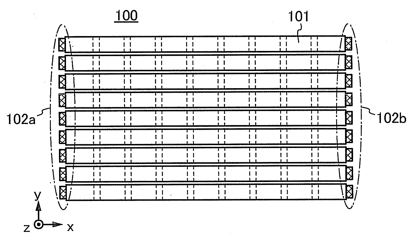
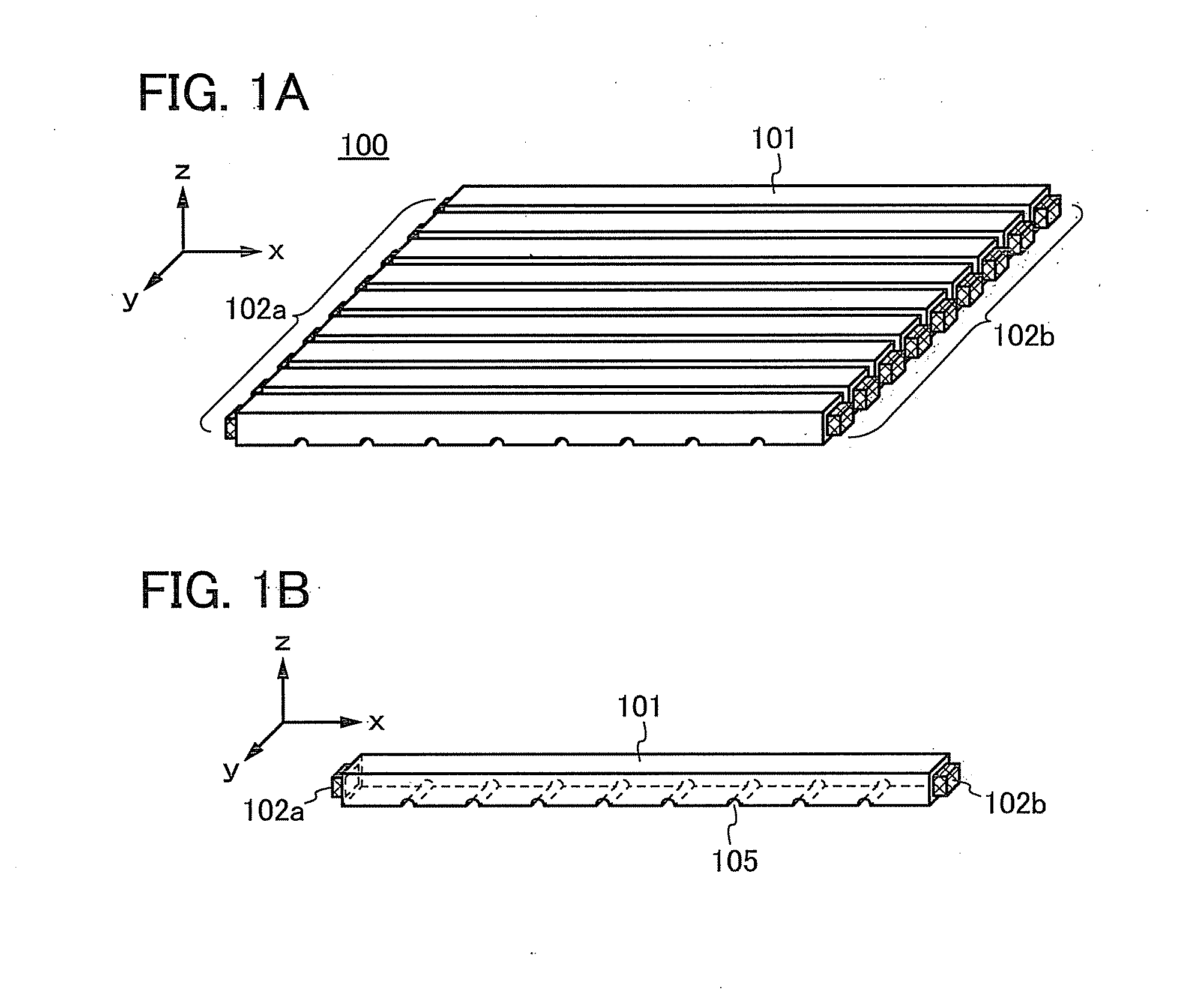
[0061]A description will be given of the structure of a backlight unit and a light guide element according to one embodiment of the present invention, with reference to FIGS. 1A and 1B and FIGS. 2A to 2C.

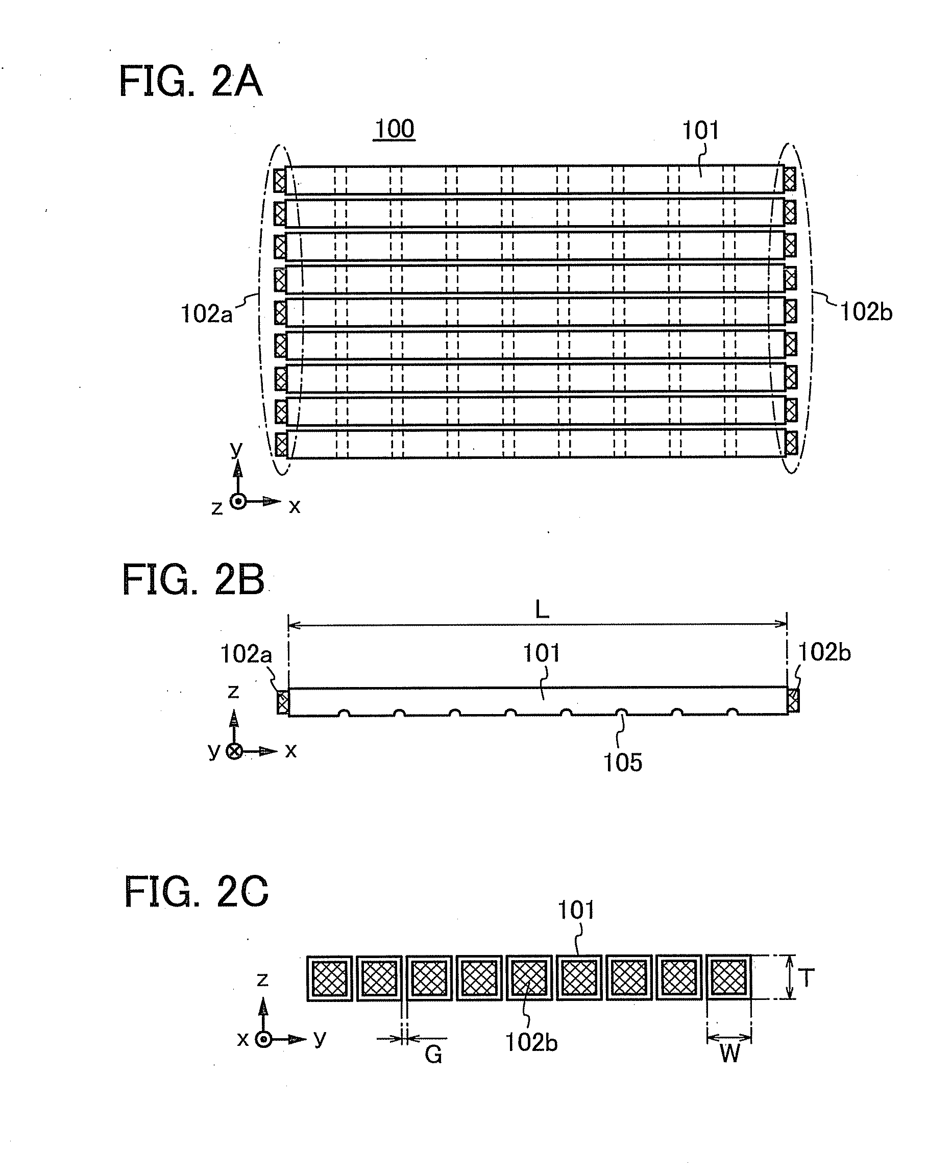
[0062]FIG. 1A is a perspective view schematically showing a backlight unit 100. FIG. 1B is a perspective view schematically showing one of light guide elements 101 included in the backlight unit 100. FIG. 2A is a schematic view of the backlight unit 100 viewed from the z direction. FIG. 2B is a schematic view of the backlight unit 100 viewed from the y direction. FIG. 2C is a schematic view of the backlight unit 100 viewed from the x direction. Note that the x direction, the y direction, and the z direction are orthogonal to one another.

[0063]The backlight unit 100 includes a plurality of light guide elements 101 arranged in the y direction. The light guide element 101 has a length L in the x direction, a width W in the y direction, and a thickness T in the z direction. The light gu...

embodiment 2

[0088]This embodiment describes an example of connection between the light guide element 101 and the light sources 102a and 102b in the backlight unit having the structure described with reference to FIGS. 1A to 1D in Embodiment 1, with reference to FIGS. 4A to 4C. The reference numerals used in FIGS. 1A to 1D will be used for the description. Note that FIGS. 4A to 4C are enlarged views of a connection point between one light guide element 101 and the light source 102b, and the same structure applies to a connection point between the light guide element 101 and the light source 102a.

[0089]FIG. 4A shows a structure in which the back of the light source 102b is provided with a reflective mirror 141. The reflective mirror 141 is disposed so as to reflect light that has failed to directly enter from the light source 102b to the light guide element 101 and to make it enter the light guide element 101. Moreover, the reflective mirror 141 allows light emitted from the end of the light gui...

embodiment 3

[0094]This embodiment describes an example of the structure of the light source 102a or 102b used in the backlight unit described with reference to FIGS. 1A and 1B in Embodiment 1, with reference to FIGS. 5A to 5I.

[0095]The light source 102a or 102b can be formed by the combination of a plurality of light sources, e.g., the combination of light sources of colors that produce white by addictive color mixture. For example, the light source 102a or 102b can be formed by the combination of a red light source (R), a green light source (G), and a blue light source (B). In other words, the light source 102a or 102b can be formed by the combination of a red light source (R), a green light source (G), a blue light source (B), and a light source of another color. The other color may be one or more of the following colors: yellow, cyan, magenta, and the like. Alternatively, the other color may be white. The light source can be a light-emitting diode, an organic EL element, or the like.

[0096]FI...


PUM


Abstract

An object is to provide a novel structure of a backlight unit using color-scan backlight drive, which can relieve a color mixture problem. A backlight unit including a plurality of light guide elements is used. The light guide element has a shape extended in the x direction. The light guide element has a shape of rectangular column. Grooves are provided on a bottom surface of the light guide element so as to traverse it in the y direction. Light sources are provided at the ends of the light guide element in the x direction to supply light into the light guide element. Light supplied into the light guide element is reflected by the grooves in the z direction, and emitted to the outside of the light guide element through the top surface. A reflective layer may be provided under the bottom surface of the light guide element.

Description

BACKGROUND OF THE INVENTION[0001]1. Field of the Invention[0002]The present invention relates to a light guide element, to a backlight unit including the light guide element, to a display device including the backlight unit, and to an electronic device provided with the display device including the backlight unit.[0003]2. Description of the Related Art[0004]Display devices ranging from large display devices such as television receivers to small display devices such as cellular phones have spread as represented by liquid crystal display devices. From now on, higher-value-added products will be needed and are being developed. In recent years, attention is attracted to the development of low-power-consumption display devices because interest in global environment is increasing and they may improve the convenience of mobile devices.[0005]Low-power-consumption display devices include display devices displaying images with a field sequential system (also called a color-sequential display ...

Claims


Application Information

Patent Timeline
IPC IPC(8): G09F13/04F21V8/00
CPCG02B6/0028G02B6/003G02B6/0031G02B6/0038G09G3/3413G02F1/133615G02F1/133621G02F2001/133622G02B6/0078G02F1/133622G02B6/00G02F1/1335
Inventor MIYAIRI, HIDEKAZUKOEZUKA, EMITANAKA, KOICHIRO
Owner SEMICON ENERGY LAB CO LTD
Why Eureka
Try Eureka