X-ray imaging apparatus

a technology of x-ray imaging and apparatus, which is applied in the direction of imaging devices, instruments, and material analysis using wave/particle radiation, can solve the problems of difficult x-ray absorption contrast methods, and achieve the effect of reducing the influence of a transmissivity distribution and exceptional quality

Inactive Publication Date: 2012-10-18
CANON KK
View PDF2 Cites 8 Cited by
  • Summary
  • Abstract
  • Description
  • Claims
  • Application Information

AI Technical Summary

Benefits of technology

[0011]In consideration of such a problem, the present invention aims to provide an X-ray imaging apparatus which can reduce an influence of a transmissivity distribution of the X-ray in the object to be detected even in the case where there is the non-uniformly distributed absorption in the object to be detected, and thus take the phase image having exceptional quality.

Problems solved by technology

However, since an X-ray absorption capability of a light element is very small, it is difficult by the X-ray absorption contrast method to take an image of living soft tissue which consists of carbon, hydrogen, oxygen and the like being constituent elements of the living body, or a soft material.

Method used


Image

  • X-ray imaging apparatus
  • X-ray imaging apparatus
  • X-ray imaging apparatus

Examples


example 1

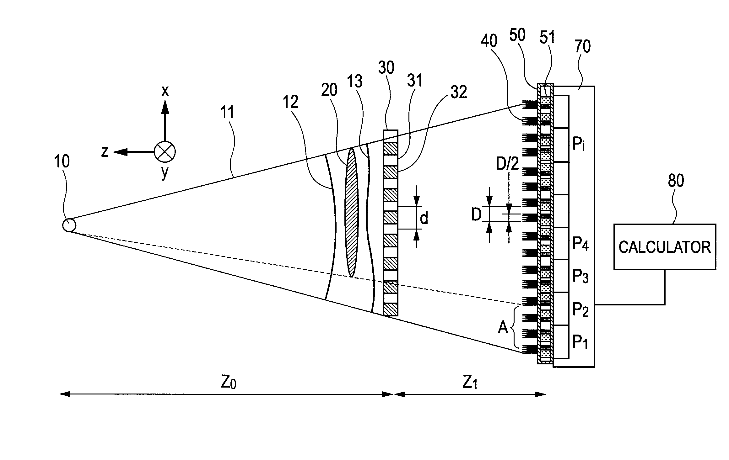
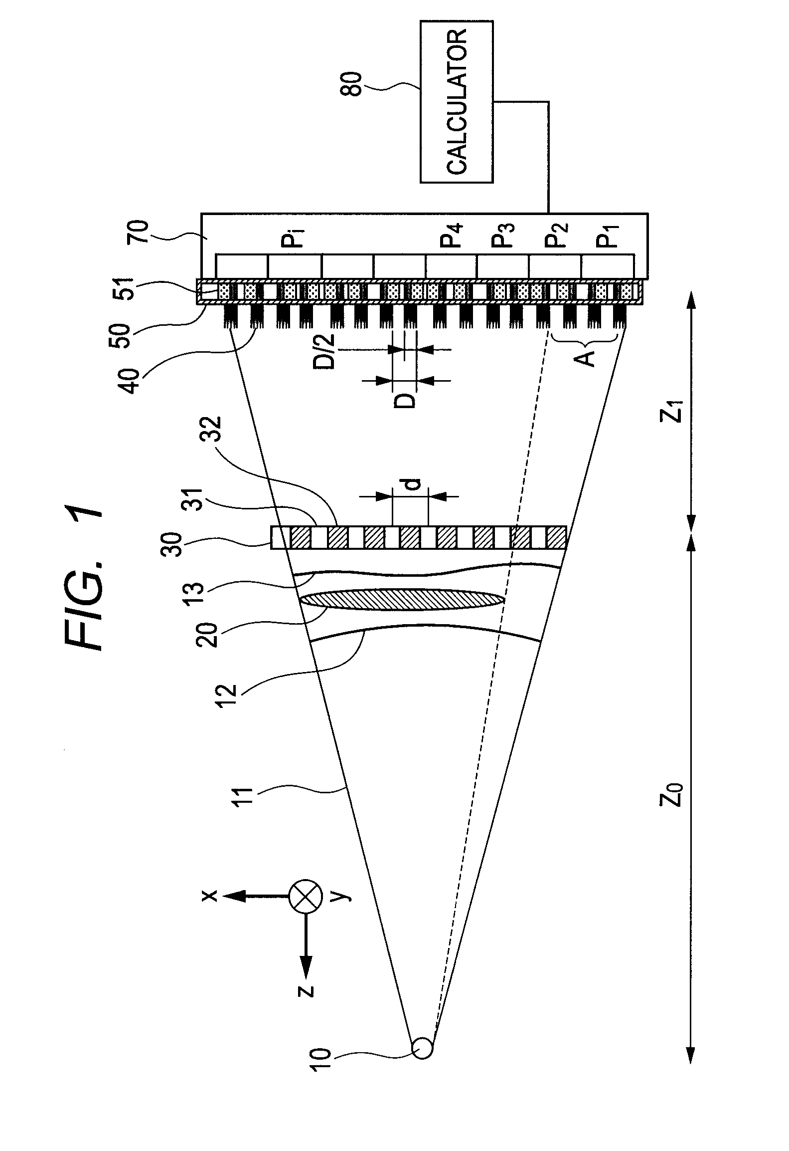
[0043]As an example 1, a construction of the X-ray imaging apparatus to which the present invention is applied will be described with reference to FIG. 1.

[0044]This drawing illustrates an X-ray source 10 which radiates an X-ray, an X-ray 11 which is radiated by the X-ray source 10, and an object 20 to be detected which is to be measured by the X-ray imaging apparatus. Further, this drawing illustrates a first grating 30 which is used to form a periodic bright-dark pattern by the transmitting X-ray, a bright section 40 of the bright-dark pattern formed by the first grating 30, and a second grating 50 which blocks a part of the bright section 40 of the bright-dark pattern.

[0045]Furthermore, this drawing illustrates an X-ray intensity detector 70 which takes and detects an X-ray image received, and pixels Pi (i=1, 2, 3, . . . ) of the X-ray intensity detector 70.

[0046]Furthermore, this drawing illustrates a calculator 80 which calculates a differential wavefront and a transmitted wavef...

example 2

[0082]An example 2 will be described with reference to FIGS. 2A, 2B, 3A, 3B, 4A and 4B.

[0083]The first grating in this example is a phase modulation grating of a phase difference π which is two-dimensionally and periodically arranged (hereinafter, called a two-dimensional n phase grating).

[0084]Therefore, also the second grating has a two-dimensional periodic structure. Since the constituent elements other than the first grating and the second grating are the same as those in the example 1, these elements respectively have the same corresponding numerals as those illustrated in FIG. 1.

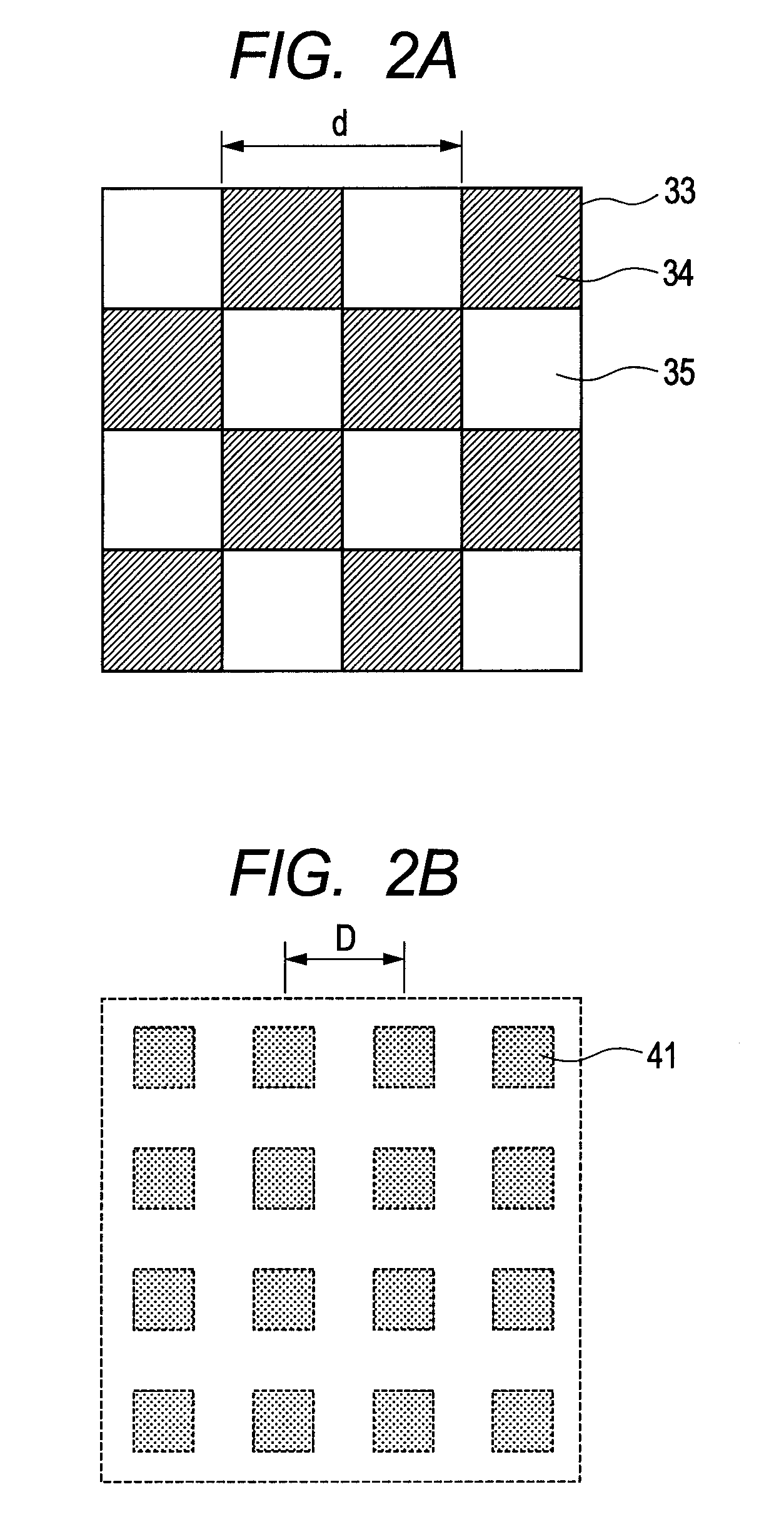
[0085]FIG. 2A is the diagram which is obtained by viewing a part of the first grating in this example from the side of the X-ray source. In the drawing, a first grating 33 includes portions 34 and 35 of which the transmission phases are mutually different by n and which are periodically arranged checkerwise.

[0086]The distance Z0 between the X-ray source and the first grating and the distance Z1 between...

example 3

[0116]An example 3 will be described with reference to FIGS. 5A, 5B, 6A and 6B.

[0117]Here, the blocking direction of the second grating in this example is different from that in the example 2, but other constituent elements are the same as those in the example 2.

[0118]FIG. 5A illustrates the structure of the second grating which is applied in a case where the period D is equivalent to the pixel period p of the X-ray intensity detector 70, and a positional relation between the blocking section of the second grating and the pixel of the X-ray intensity detector 70.

[0119]Here, respective portions Pij (i, j=1, 2, 3, . . . ) correspond to the pixels of the X-ray intensity detector 70, in which the borders of the pixels are indicated by the dotted lines, and a portion 56 corresponds to the second grating.

[0120]A hatched portion 57 corresponds to the blocking section of the second grating 56, and a non-hatched portion corresponds to the light transmitting section. The blocking sections and...


PUM

PropertyMeasurementUnit
transparencyaaaaaaaaaa
densityaaaaaaaaaa
phase contrastaaaaaaaaaa

Abstract

An X-ray imaging apparatus which takes an image of an object to be detected, comprises: a first grating to form a periodic bright-dark pattern by a Talbot effect, based on an X-ray from an X-ray source; a second grating, disposed at a position where the bright-dark pattern is formed, to block a part of the bright-dark pattern; a detector to detect an X-ray intensity distribution of the X-ray which passed through the second grating; and a calculator to calculate phase information of the X-ray based on the detected X-ray intensity distribution, wherein the second grating includes a first region having a first blocking pattern and a second region having a second blocking pattern, and a direction in which the first blocking pattern blocks a bright section of the bright-dark pattern is different from a direction in which the second blocking pattern blocks the bright section of the bright-dark pattern.

Description

TECHNICAL FIELD[0001]The present invention relates to an X-ray imaging apparatus.BACKGROUND ART[0002]An X-ray has high material transparency, and can achieve imaging with high spatial resolution. For these reasons, the X-ray is used for a nondestructive inspection of an object as industrial utilization, X-raying as medical utilization, and the like.[0003]That is, by the X-ray in the above utilization, a contrast image is formed by using a difference of absorption in a case where the X-ray transmits through an object or a living body, due to constituent elements and density differences of the object or the living body. It should be noted that such a process is called an X-ray absorption contrast method. However, since an X-ray absorption capability of a light element is very small, it is difficult by the X-ray absorption contrast method to take an image of living soft tissue which consists of carbon, hydrogen, oxygen and the like being constituent elements of the living body, or a so...

Claims


Application Information

Patent Timeline
Patent Type & Authority Applications(United States)
IPC IPC(8): G01N23/04
CPCG01N23/046G01N23/20075G01N2223/064G01N2223/419G21K2207/005A61B6/484G21K1/06
Inventor OUCHI, CHIDANE
Owner CANON KK
Why Eureka
Try Eureka