Axial gap motor and pump device

a technology of axial gap motor and pump device, which is applied in the direction of piston pumps, magnetic circuit rotating parts, magnetic circuit shape/form/construction, etc., can solve the problems of increasing magnetic resistance, increasing magnetic resistance, and insufficient contact area secured, so as to increase the contact area and increase the surface area. , the effect of increasing the magnetic flux density

Active Publication Date: 2012-10-18
FUJITSU GENERAL LTD
View PDF6 Cites 16 Cited by
  • Summary
  • Abstract
  • Description
  • Claims
  • Application Information

AI Technical Summary

Benefits of technology

[0023]According to the invention described in claim 1, when the surface area of the contact surfaces that come into contact with the yoke strip when yoke strips are coupled to each other is represented as As and the projected area of the lateral surface of the yoke strip viewed from the circumferential direction is represented as Ap, the contact surfaces are formed to satisfy the relation As>Ap. Consequently, since the contact surfaces can be surely brought into contact with each other, it is possible to secure a magnetic flux path.
[0024]According to the inventions described in claims 2 and 3, the contact surface includes at least two or more surfaces. Consequently, it is possible to easily increase a contact area by providing two or more contact surfaces. Further, the contact surface includes the arcuate surface. Consequently, it is possible to further increase the surface area than a flat surface and increase magnetic flux density.
[0025]According to the invention described in claim 4, the positional deviation preventing means for preventing positional deviation of the contact surfaces is provided on the contact surface. Consequently, even if external force is applied, since the contact surfaces are coupled by the positional deviation preventing means, it is possible to surely maintain the coupling.
[0026]According to the invention described in claim 5, the flange on the teeth surface side of the pair of flange sections of the insulator attached to the core member is formed to be lower than the teeth surface in the axis line direction. Consequently, since the teeth surface is located in the highest position, it is possible to reduce a gap between the teeth surface and the rotor and reduce an axial direction dimension.
[0027]According to the invention described in claim 6, the locking shaft provided on the other end side in the circumferential direction of the flange section is formed to have the axis line direction height lower than the teeth surface in the axis line direction. Consequently, since the locking shaft is not an obstacle, it is possible to further reduce the gap between the teeth surface and the rotor.
[0028]According to the invention described in claim 7, when the core members are coupled to one another, a part of the flange sections of the core members adjacent to each other are arranged to overlap each other along the axis line direction. The contact surface of the flange section and the contact surface of the yoke strip are arranged in opposite directions with respect to the axis line direction such that the contact surface of the flange section comes into contact from any one side in the axis line direction and the contact surface of the yoke strip comes into contact from the other side in the axis line direction. Therefore, it is possible to surely prevent the core member from coming off in the axis line direction.

Problems solved by technology

However, in the case of the divided core-type axial gap motor explained above, since the end faces of the yoke strips of the core members adjacent to each other are set in contact with each other to form one magnetic circuit, it is likely that a contact area cannot be secured sufficiently large and magnetic resistance increases.
If the contact area cannot be secured large, for example, since the end faces in contact with each other tend to be separated when receiving a shock, it is likely that the magnetic resistance further increases and magnetic loss of the motor increases.
However, when the divided core-type axial gap motor is used in the pump device, there is a problem explained below.
Therefore, since a part of the flange section further projects than a teeth surface, when the axial gap motor is incorporated in the motor chamber of the pump device, a gap between a teeth surface of the stator and a magnet surface of the rotor inevitably increases.

Method used


Image

  • Axial gap motor and pump device
  • Axial gap motor and pump device
  • Axial gap motor and pump device

Examples


Embodiment Construction

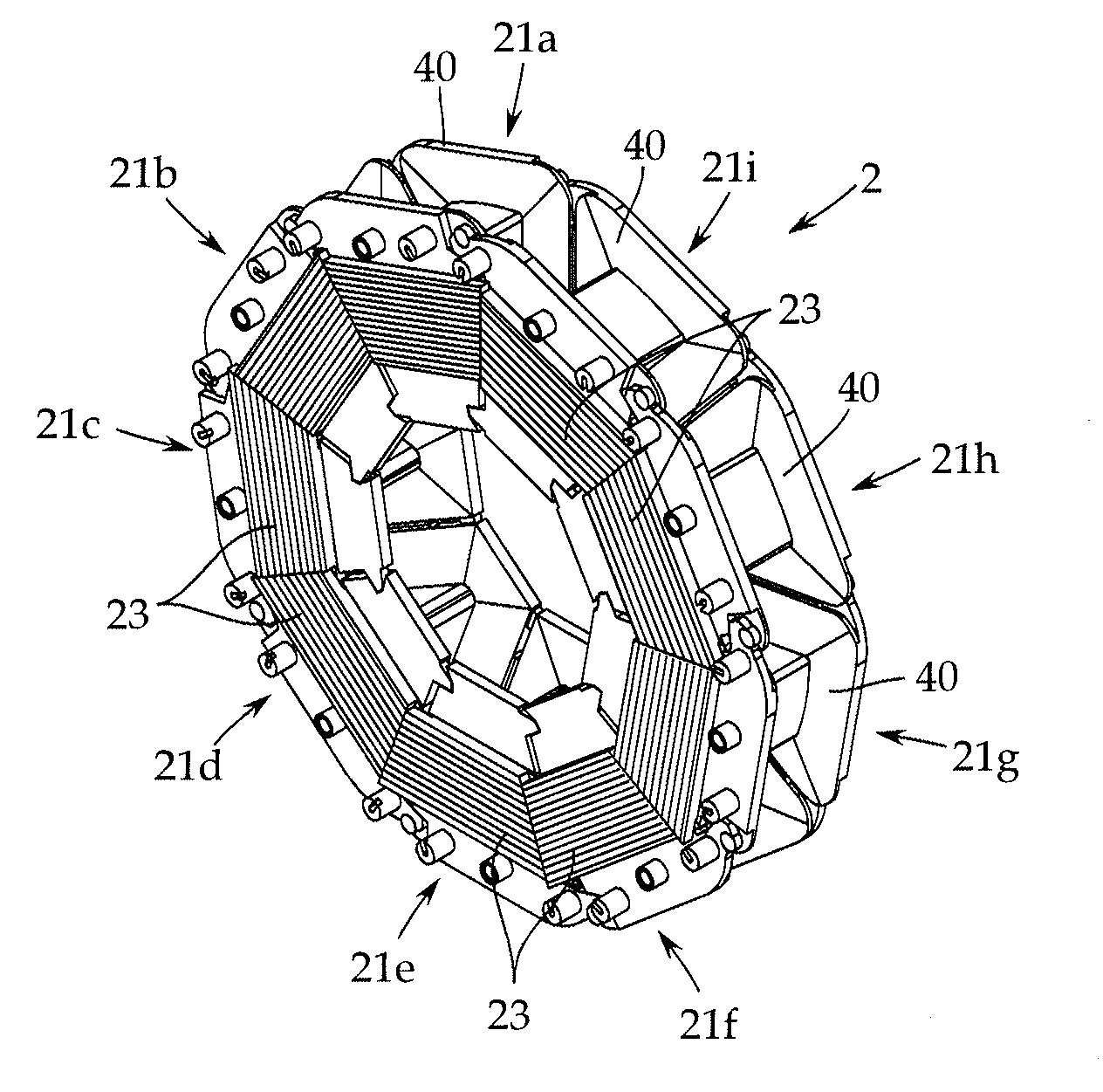
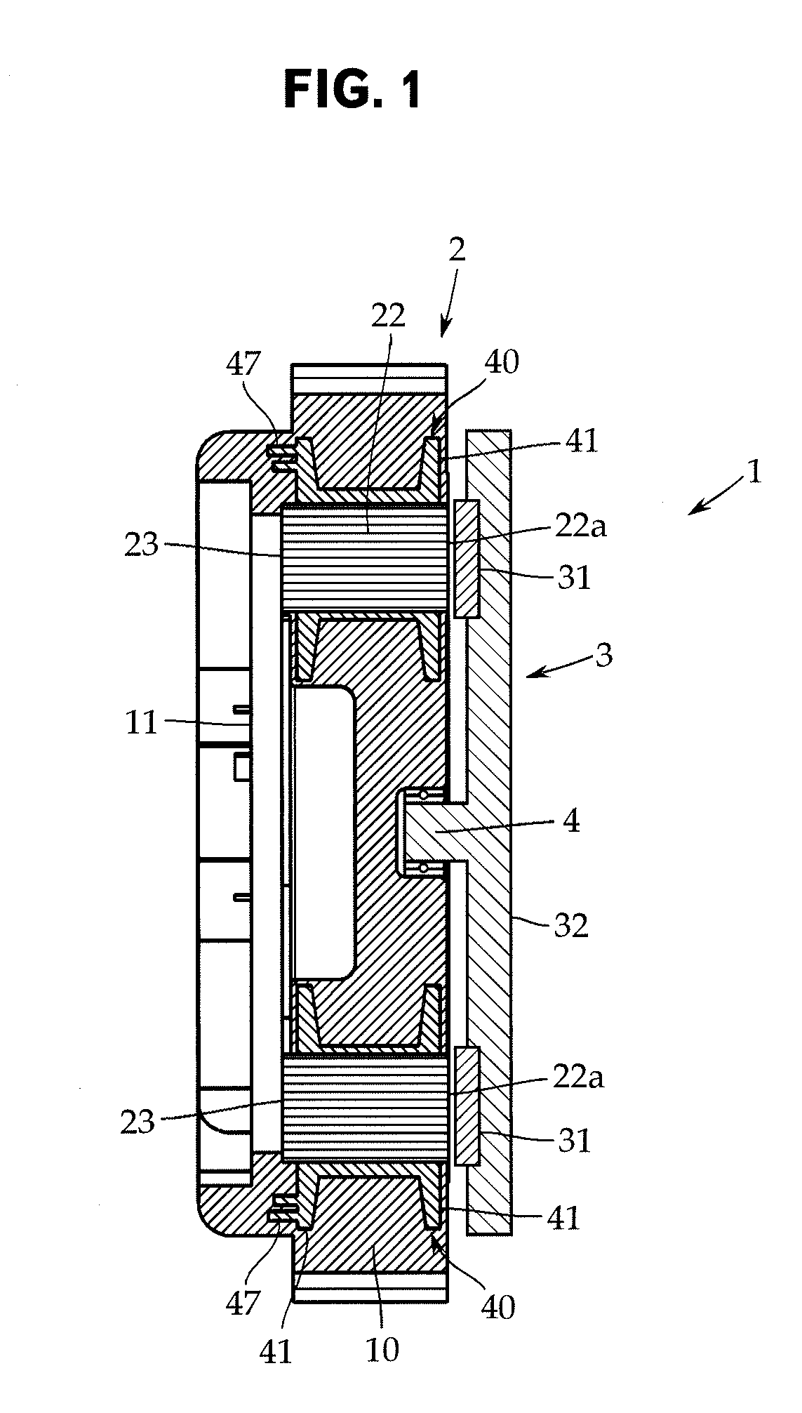
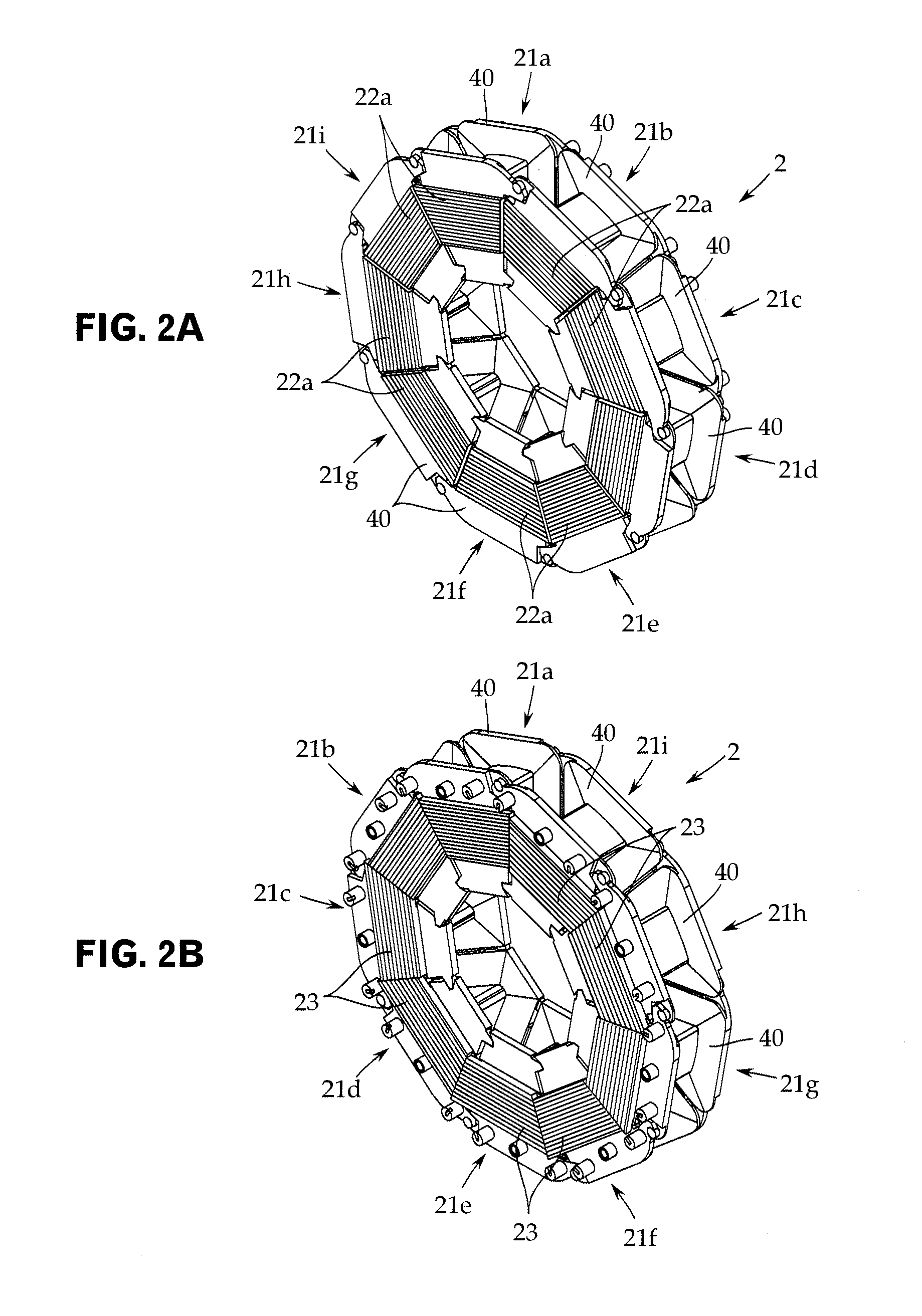
[0050]An embodiment of the present invention is explained below with reference to the drawings. However, the present invention is not limited to the embodiment. As shown in FIG. 1, this axial gap motor 1 includes a stator 2 that forms an outer shell with a resin compact 10 excluding teeth surfaces 22a of the stator 2 and end faces of yoke strips 23 and a rotor 3 arranged to be opposed to one surface (in FIG. 1, the right lateral surface) of the stator 2 with a predetermined gap (air gap). A rotor output shaft 4 is coaxially fixed to the rotor 3.

[0051]The stator 2 is annularly formed centering on the axis line direction of the rotor output shaft 4 and is molded integrally with the resin compact 10 by insert molding. On the counter rotor side (in FIG. 1, the left lateral surface side) of the stator 2, a substrate pedestal 11 on which a not-shown control board is fixed is integrally molded by the resin compact 10.

[0052]In the rotor 3, a large number of magnets 31 are provided in the ci...


PUM


Abstract

Disclosed are a single rotor-type axial gap motor with low magnetic loss and high output, and a pump device using the axial gap motor. A first contact surface (231) is provided on the lateral surface in one circumferential direction of a yoke strip (23), and a second contact surface (232) is provided on the lateral surface in the other circumferential direction of the yoke strip (23), wherein the first contact surface (231) and the second contact surface (232) are aligned with each other. Defining As1 and As2 as the surface areas (As) of the first and second contact surfaces (231, 232), and Ap1 and Ap2 as the projected surface areas (Ap) of the lateral surfaces of the aforementioned yoke strip seen from the circumferential direction, it holds that As>Ap.

Description

TECHNICAL FIELD[0001]The present invention relates to a single rotor-type axial gap motor in which a rotor and a stator are arranged to be opposed to each other with a predetermined gap along the axis line direction of a rotor output shaft and, more particularly, to an axial gap motor in which yoke strips included in a yoke section of a stator core are magnetically surely coupled to each other to realize higher efficiency.BACKGROUND ART[0002]For example, as disclosed in Patent Literature 1, the axial gap motor is a motor in which a rotor is arranged to be opposed to the lateral surface in one direction or each of the lateral surfaces in both directions of a stator with a predetermined gap. Compared with a radial gap motor, it is possible to reduce the overall length in a rotating shaft direction irrespective of the magnitude of an output.[0003]The stator is formed by plural core members annularly coupled to one another centering on the axis line direction of a rotor output shaft. Co...

Claims


Application Information

Patent Timeline
Patent Type & Authority Applications(United States)
IPC IPC(8): H02K3/34H02K1/12F04B35/04H02K1/18
CPCF04D13/0666F04D13/064F04D13/0626H02K1/148
Inventor MATSUZAKI, HIROKAZUMAEYAMA, KENFUJIMOTO, MOTOAKIKOJIMA, TOMONORI
Owner FUJITSU GENERAL LTD
Why Eureka
Try Eureka