System, method and apparatus for thermal energy management in a roof

a technology of thermal energy management and roof, applied in the field of roofs, can solve the problems of low cooling energy cost, product heating penalties, and not designed for managing solar hea

Inactive Publication Date: 2012-10-25
CERTAINTEED CORP
View PDF30 Cites 43 Cited by
  • Summary
  • Abstract
  • Description
  • Claims
  • Application Information

AI Technical Summary

Benefits of technology

[0010]Embodiments of a system, method and apparatus for thermal energy management of a roof are disclosed. For example, a roof product may comprise a thermal heat storage layer, a vent layer having channels for transferring excess heat through an entire length of the r

Problems solved by technology

This issue is particularly problematic for cold to moderate climate regions, and for seasons where the day and night temperature differences are significant, such as in the spring or fall seasons.
Although such products lower cooling energy costs, particularly in warmer climates, they are not designed for

Method used


Image

  • System, method and apparatus for thermal energy management in a roof
  • System, method and apparatus for thermal energy management in a roof
  • System, method and apparatus for thermal energy management in a roof

Examples


Embodiment Construction

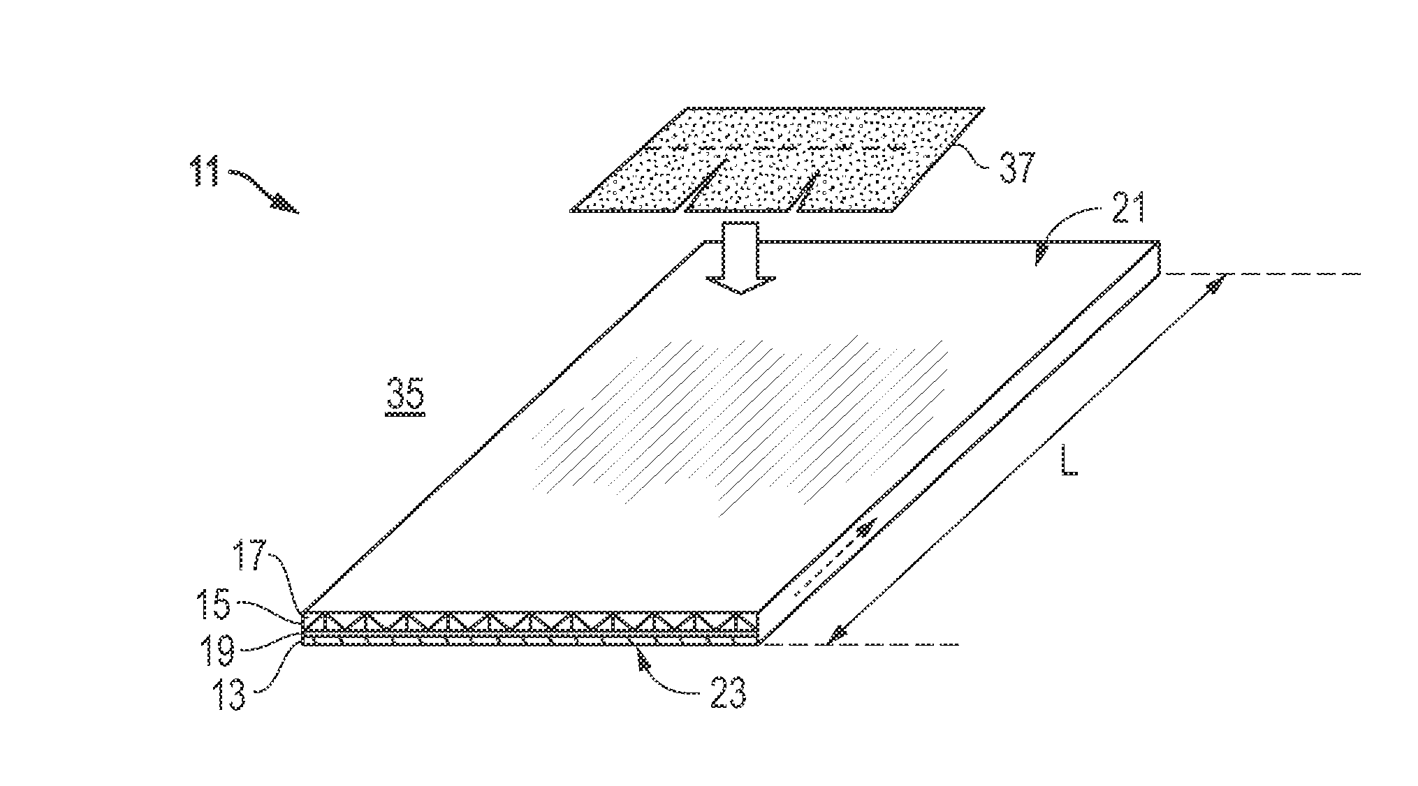
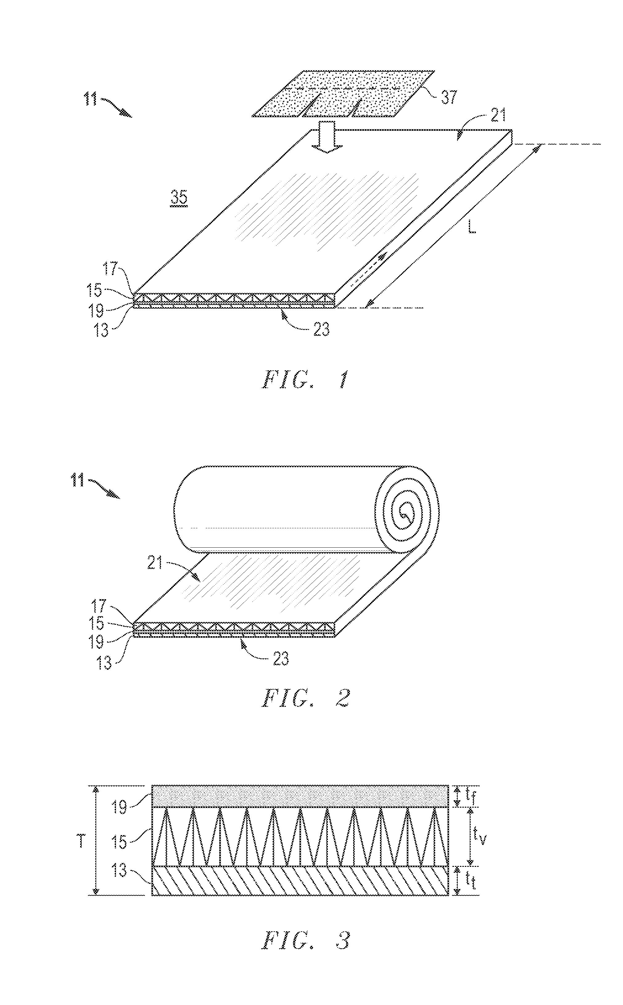
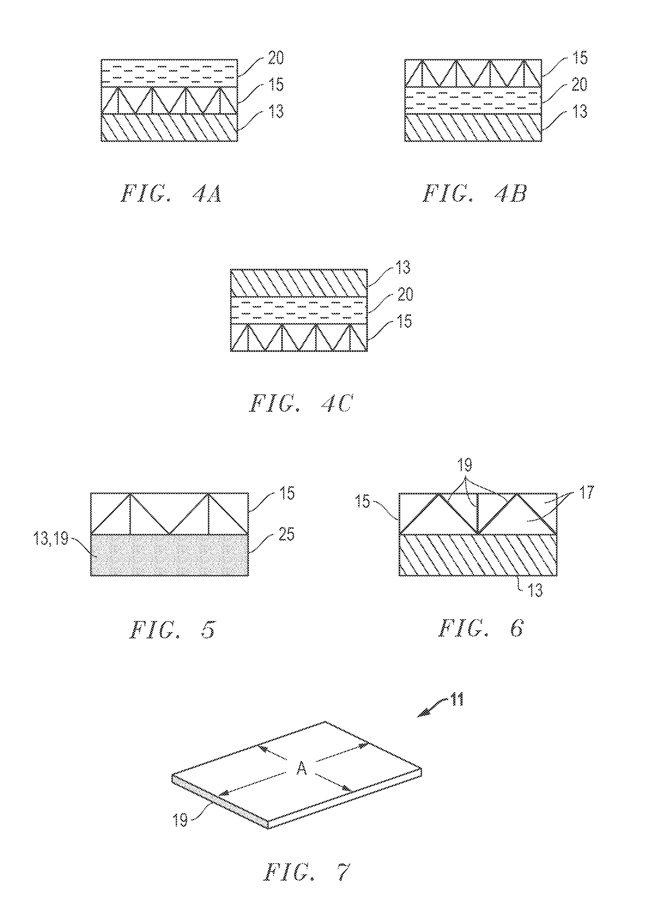
[0025]Embodiments of a system, method and apparatus for thermal energy management of a roof are disclosed. For example, a roof product 11 may comprise a sheet or a panel (which may be rigid; see, e.g., FIG. 1) or a flexible roll of material (see, e.g., FIG. 2) having a plurality of layers and / or materials. In some embodiments, the roof product 11 comprises a thermal heat storage layer 13, a vent layer 15 having channels 17 for transferring excess heat through an entire length L of the roof product 11, and a flame retardant 19 to suppress fire through the vent layer 15. The thermal heat storage layer 13, vent layer 15 and flame retardant 19 form a unitary structure as shown.

[0026]In other embodiments, the roof product further comprises outer skin layers comprising an uppermost layer 21 and a lowermost layer 23, between which are located the thermal heat storage layer 13, the vent layer 15 and the flame retardant 19. As shown in FIGS. 1 and 2, the flame retardant 19 is located between...


PUM

PropertyMeasurementUnit
Temperatureaaaaaaaaaa
Lengthaaaaaaaaaa

Abstract

A roof product has a thermal heat storage layer, a vent layer with channels for transferring excess heat through a length of the roof product, and a flame retardant to suppress fire through the vent layer. These three materials form a unitary structure. The roof product may have a radiant layer, the thermal heat storage layer and the vent layer to form the unitary structure. The roof products are assembled in an abutting configuration on the roof of a building. The vent layer vents excess heat from an eave of the roof up to a ridge of the roof and out to atmosphere. The roof products manage thermal energy in the roof by storing thermal heat with the unitary roof product during a heating cycle; venting excess heat through the unitary product; and releasing the stored thermal heat from the unitary product into or out of the building during a cooling cycle.

Description

[0001]This application claims priority to and the benefit of U.S. Provisional Patent Application No. 61,477,941, filed Apr. 21, 2011, which is incorporated herein by reference in its entirety.BACKGROUND OF THE INVENTION[0002]1. Field of the Disclosure[0003]The present invention relates in general to roofing and, in particular, to a system, method and apparatus for thermal energy management in a roof.[0004]2. Description of the Related Art[0005]Typical residential roofs in the North America have bitumen-based roofing materials that provide satisfactory water shedding, long term durability and have aesthetic appeal. Most asphaltic roofing materials are colored in traditional dark earth tones. These colors absorb significant amounts of solar heat during hot summer times, which penetrates through the roof deck, attic and ceiling into the house. The heat penetration increases the need for cooling energy for the indoor comfort of residence occupants.[0006]On the other hand, these types of...

Claims


Application Information

Patent Timeline
IPC IPC(8): E04B7/00B32B3/12E04B1/38B32B3/10E04B1/62E04B1/94
CPCE04D13/1618E04D13/17B32B3/10B32B3/12B32B2419/06Y10T428/24149F24J2/045F24J2/34Y02E10/44Y10T428/24331Y02B10/20C09K21/02C09K21/04C09K21/08E04D1/30E04D2001/309F24S20/67F24S60/00Y02E10/40B32B3/30B32B2250/05B32B2307/30B32B2307/3065E04B1/7612E04B1/80E04B1/94E04B1/941E04D3/34E04D3/357E04D5/10E04D5/144
Inventor SHIAO, MING L.KALKANOLGU, HUSNU M.JACOBS, GREGORY F.
Owner CERTAINTEED CORP
Why Eureka
Try Eureka