Ultrasonic coupler assembly

a technology of ultrasonic couplers and couplers, which is applied in the direction of liquid/fluent solid measurement, magnetic property measurement, instruments, etc., can solve the problems of increasing the cost of ultrasonic transducers, and significantly more expensive ultrasonic transducers, so as to improve the quality of ultrasonic signal passing, reduce the required temperature rating, and increase the number of applications

Active Publication Date: 2012-10-25
BAKER HUGHES INC
View PDF8 Cites 20 Cited by
  • Summary
  • Abstract
  • Description
  • Claims
  • Application Information

AI Technical Summary

Benefits of technology

[0006]An ultrasonic coupler assembly for coupling an ultrasonic transducer to a pipe wall is disclosed, wherein an ultrasonic coupler is configured using three quadrilateral sections to reduce the temperature extreme to which the ultrasonic transducer is exposed and to improve the quality of the ultrasonic signal passing through the ultrasonic coupler. An advantage that may be realized in the practice of some disclosed embodi

Problems solved by technology

The ultrasonic transducers attached to those extreme temperature pipe walls are heated or cooled by the extreme temperatures of the pipes and therefore must be constructed of proper materials that increase the cost of these ultrasonic transducers.
For example, an ultrasonic transducer rated at +200° C. or greater can be significantly more expensive than an ultrasonic transducer rated at +100° C. Similarly, an ultrasonic transducer rated at −200° C. or less can be significantly more expensive than an ultrasonic transducer rated at −100° C. In addition, even when constructed of the proper materials for extreme temperature applications, an ultrasonic transducer consistently

Method used


Image

  • Ultrasonic coupler assembly
  • Ultrasonic coupler assembly
  • Ultrasonic coupler assembly

Examples


Embodiment Construction

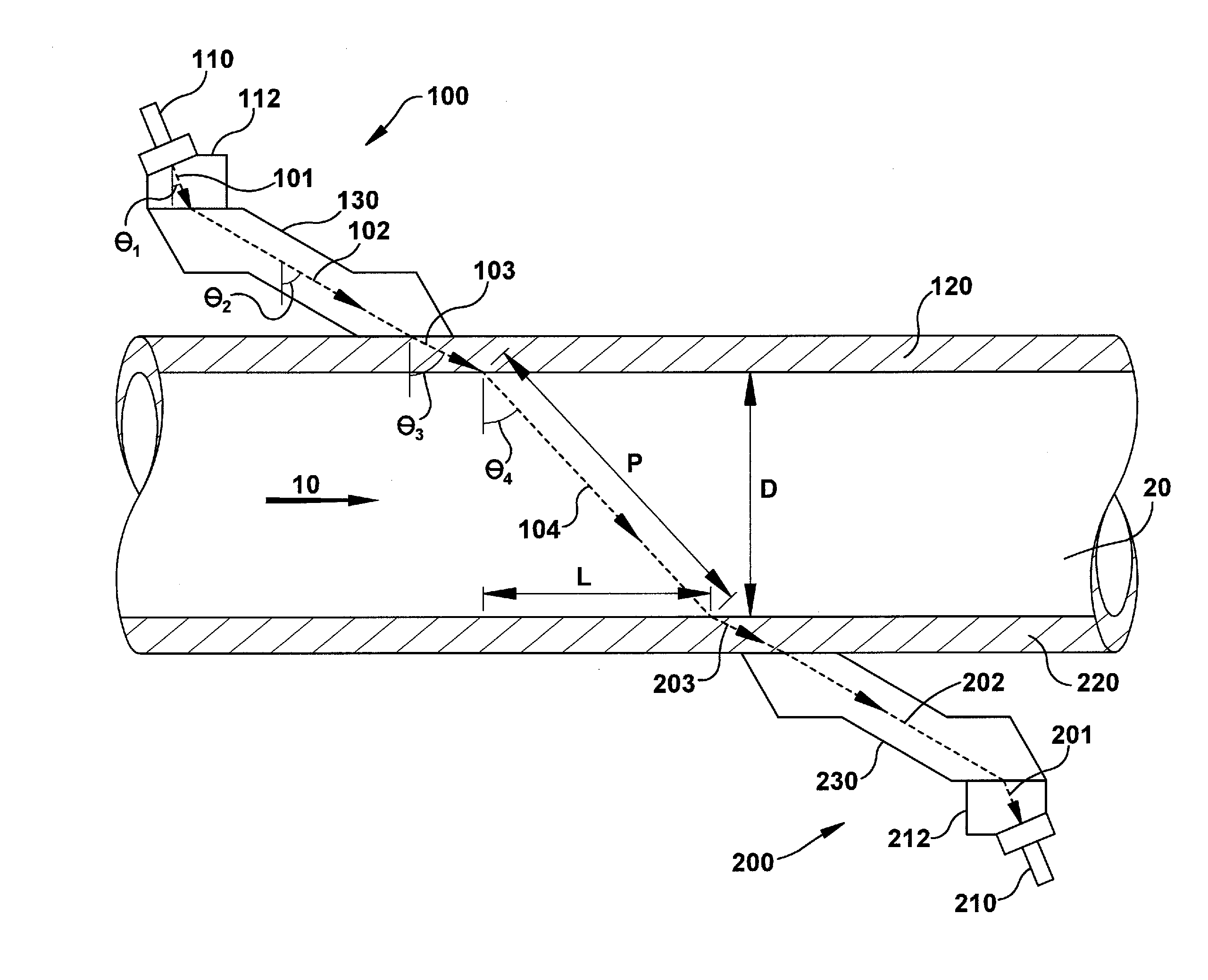
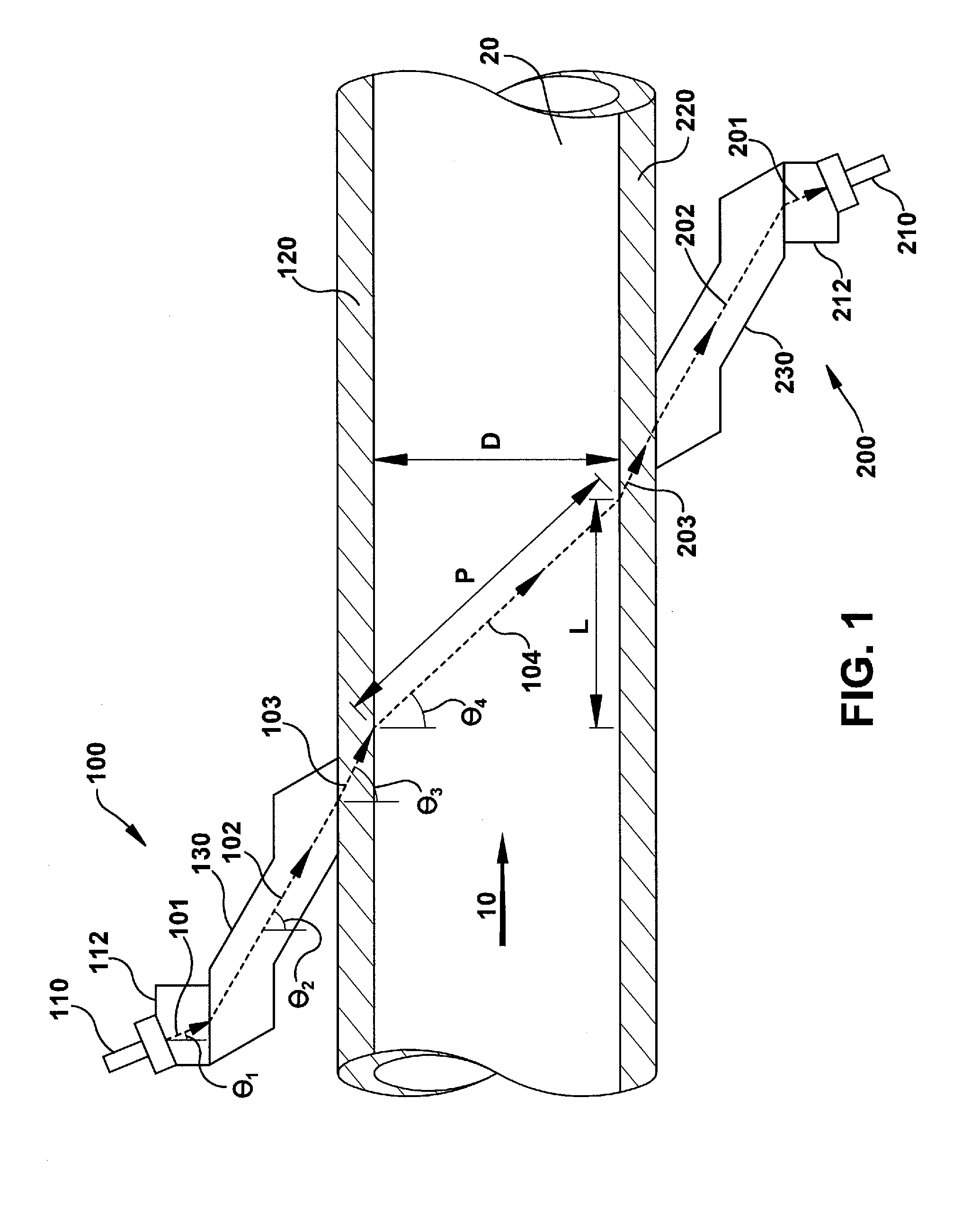
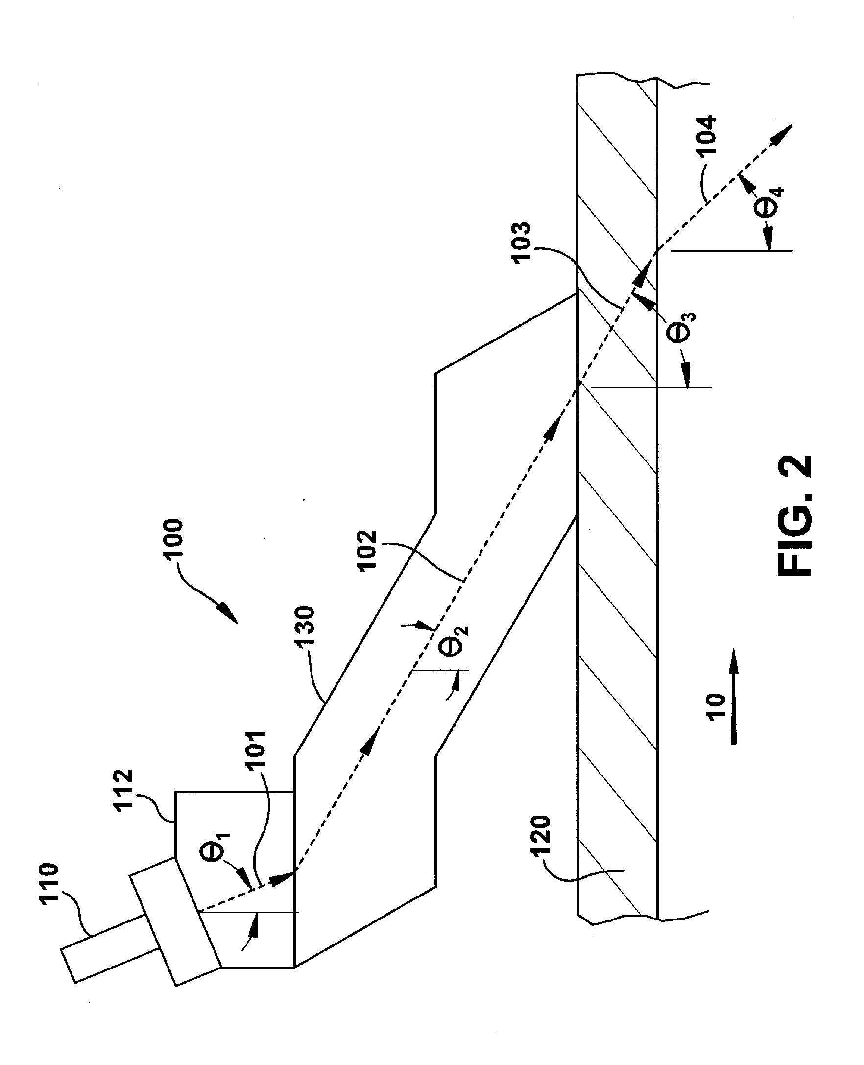
[0017]An ultrasonic coupler assembly for coupling an ultrasonic transducer to a pipe wall is disclosed, wherein an ultrasonic coupler is configured using three quadrilateral sections to reduce the temperature extreme to which the ultrasonic transducer is exposed and to improve the quality of the ultrasonic signal passing through the ultrasonic coupler.

[0018]FIG. 1 is a cross-section of an ultrasonic flow meter installed on a pipe 20 employing transit time flow metering to determine the flow rate of a fluid in an exemplary embodiment of the invention. FIG. 2 is an enlarged cross-section view of a portion of the ultrasonic flow meter of FIG. 1 showing an ultrasonic coupler assembly 100 installed on a pipe wall 120 in an exemplary embodiment of the invention. Although FIG. 1 shows a single pair of ultrasonic transducers 110, 210 forming a single ultrasonic path 104 through the fluid, it will be understood by a person of ordinary skill in the art that two or more pairs of ultrasonic tra...


PUM


Abstract

An ultrasonic coupler assembly for coupling an ultrasonic transducer to a pipe wall is disclosed, wherein the ultrasonic coupler is configured using three quadrilateral sections to reduce the temperature extreme to which the ultrasonic transducer is exposed and to improve the quality of the ultrasonic signal passing through the ultrasonic coupler.

Description

BACKGROUND OF THE INVENTION[0001]This invention relates generally to ultrasonic flow rate measurement, and more particularly to an ultrasonic coupler assembly.[0002]Ultrasonic flow meters are used to determine the flow rate (i.e., mean pipe flow rate (Vm)) of a variety of fluids (e.g., liquids, gases, etc.) in the fluid flowing in pipes of different sizes and shapes. In one type of ultrasonic flow meter employing transit time flow metering, one or more pairs of ultrasonic transducers can be attached to the exterior of the pipe wall, where each pair can contain ultrasonic transducers located upstream and downstream from each other, forming an ultrasonic path between them. Each ultrasonic transducer, when energized, transmits an ultrasonic signal (e.g., a sound wave) along an ultrasonic path through the flowing fluid that is received by and detected by the other ultrasonic transducer. The path velocity (i.e., path or chord velocity (Vp)) of the flowing fluid averaged along an ultrason...

Claims


Application Information

Patent Timeline
IPC IPC(8): G01N29/28
CPCG01F1/668G01F1/662
Inventor AO, XIAOLEI SHIRLEYKHRAKOVSKY, OLEG ALEXANDERFRAIL, CHRISTOPHER ALANMA, YUE
Owner BAKER HUGHES INC
Why Eureka
Try Eureka