Solid-state imaging device and method for manufacturing the same

a solid-state imaging and imaging device technology, applied in the direction of lenses, instruments, optical elements, etc., can solve the problems of color irregularity or sensitivity unevenness, and achieve the effect of increasing the thickness of the color filter in the pixel region

Inactive Publication Date: 2012-10-25
PANASONIC SEMICON SOLUTIONS CO LTD
View PDF1 Cites 35 Cited by
  • Summary
  • Abstract
  • Description
  • Claims
  • Application Information

AI Technical Summary

Benefits of technology

[0009]An upper surface of an organic material is inclined from the peripheral circuit region to the pixel region by an influence of a step when the organic material is applied to form a color filter. As a result, a thickness of the color filter in the pix

Problems solved by technology

SUMMARY However, solid-state imaging device 900 described in the Unexamined Japanese Patent Publication No. 3-282403 has a problem in that filters 907

Method used


Image

  • Solid-state imaging device and method for manufacturing the same
  • Solid-state imaging device and method for manufacturing the same
  • Solid-state imaging device and method for manufacturing the same

Examples


first exemplary embodiment

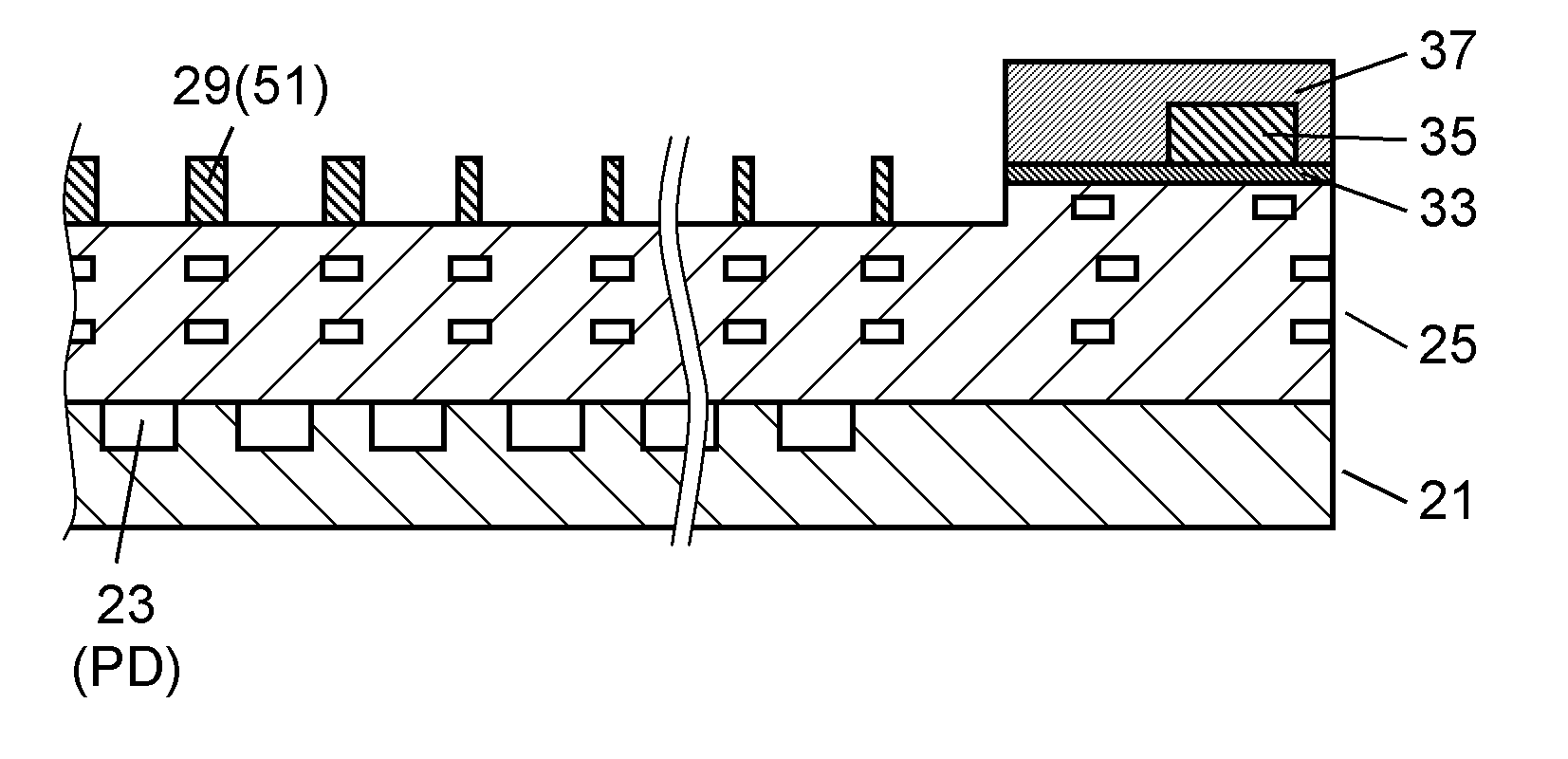
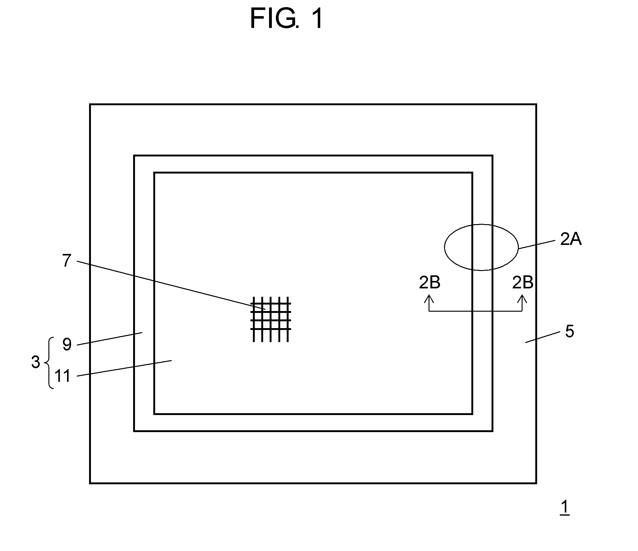
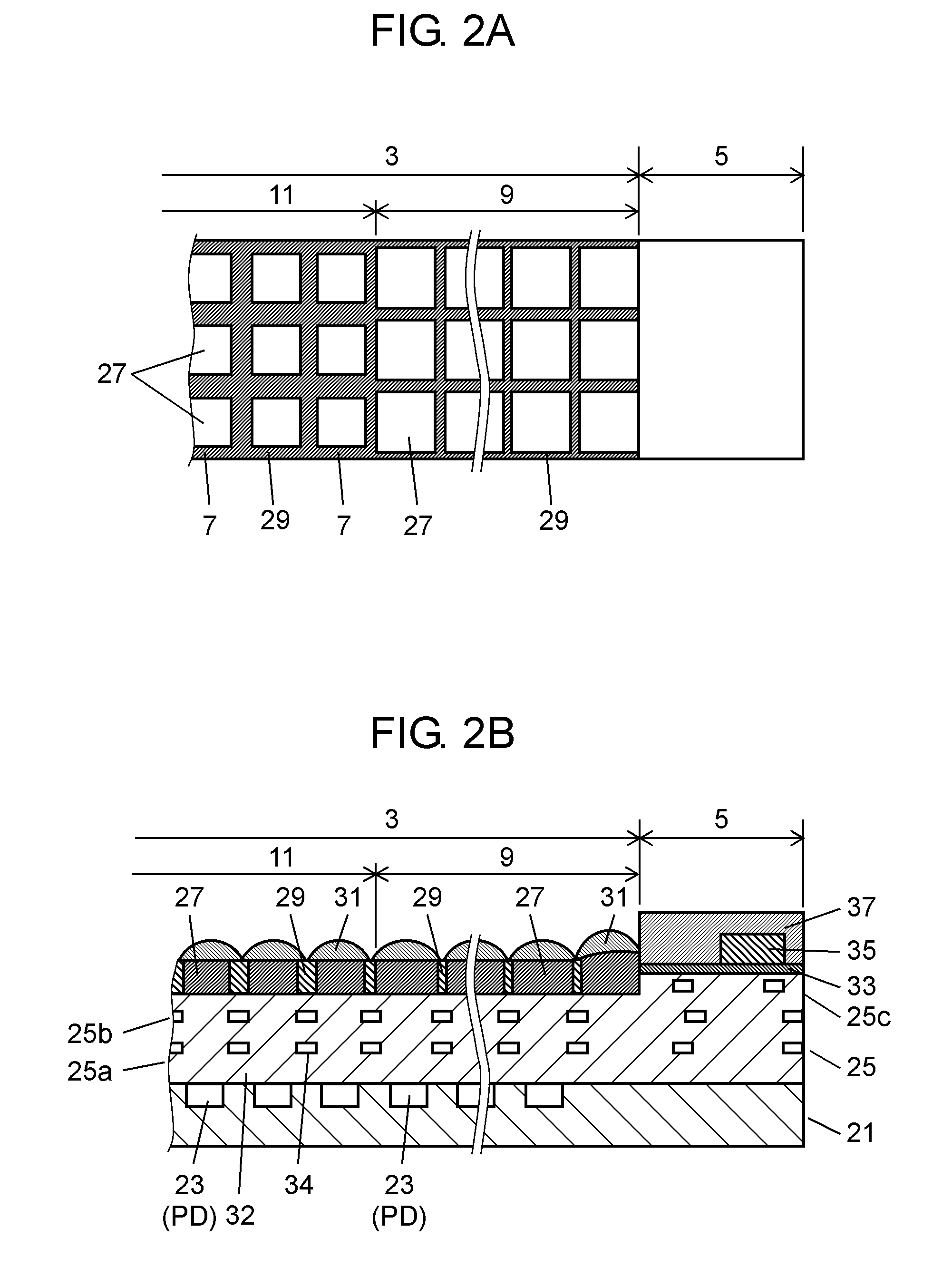
[0036]Solid-state imaging device 1 according to the present exemplary embodiment includes semiconductor substrate 21, and wiring layer 25 to be a ground layer which is formed on semiconductor substrate 21 and has an upper surface corresponding to pixel region 3, the upper surface being lower than an upper surface corresponding to peripheral circuit region 5 as shown in FIGS. 1, 2A and 2B. There are provided a plurality of color filters 27 disposed two-dimensionally on the upper surface corresponding to pixel region 3 in wiring layer 25 to be the ground layer and partition wall 29 disposed between respective color filters 27. In an orthogonal section to the upper surface corresponding to pixel region 3 in wiring layer 25 to be the ground layer, an occupied area of partition wall 29 disposed in invalid pixel region 9 to be an outer portion of the pixel region 3 adjacent to peripheral circuit region 5 is smaller than that of partition wall 29 disposed in valid pixel region 11 to be a c...

second exemplary embodiment

[0087]In the first exemplary embodiment, partition wall 29 is constituted by resin material 51, and furthermore, partition wall 29 has a width which is varied in a cross section between valid pixel region 11 and invalid pixel region 9.

[0088]However, a material of the partition wall is not restricted to the resin material but another material, for example, an inorganic material may be utilized. In addition, it is sufficient that the partition wall 29 is formed in at least a valid pixel region 11 and the partition wall 29 in the invalid pixel region 9 can suppress a film thickness unevenness caused by a flow of a filter forming resin due to a step between the pixel region 3 and a peripheral circuit region 5 in a formation of a color filter 27 and does not need to be always provided.

[0089]As shown in FIG. 6A and 6B, solid-state imaging device 101 according to a second exemplary embodiment includes semiconductor substrate 21, and wiring layer 25 to be a ground layer which is formed on s...

third exemplary embodiment

[0101]In the first and second exemplary embodiments, wiring layer 25 is disposed on light receiving part 23 of semiconductor substrate 21. However, in order to enhance a light propagation efficiency of light incident on a microlens to a photodiode, a portion positioned above the photodiode in the wiring layer may have an optical waveguide including a core part formed by a material having a higher refractive index than an interlayer insulating film of the wiring layer.

[0102]Description will be given by taking solid-state imaging device 201 including the optical waveguide as a third exemplary embodiment.

[0103]FIG. 7 is an enlarged view showing a single pixel part of solid-state imaging device 201 according to the third exemplary embodiment.

[0104]Solid-state imaging device 201 has wiring layer 203 on semiconductor substrate 21. Wiring layer 203 has a two-layer structure including first layer 203a and second layer 203b in pixel region 3, and each of layers 203a and 203b has insulating f...


PUM


Abstract

There are provided semiconductor substrate, ground layer formed on semiconductor substrate and having an upper surface corresponding to pixel region, the upper surface being lower than an upper surface corresponding to peripheral circuit region, a plurality of color filters disposed two-dimensionally on the upper surface corresponding to pixel region in ground layer, and partition wall provided between color filters. In a section which is orthogonal to the upper surface corresponding to pixel region in ground layer, an occupied area of partition wall provided in outer portion disposed in contact with peripheral circuit region is smaller than that of partition wall provided in central portion of pixel region.

Description

BACKGROUND[0001]1. Technical Field[0002]The present invention relates to a solid-state imaging device and a method for manufacturing the same, and more particularly to a solid-state imaging device using a partition wall between color filters and a method for manufacturing the same.[0003]2. Description of the Related Art[0004]In a solid-state imaging device in which color filters are formed corresponding to light receiving parts formed on a semiconductor substrate respectively, there is the technique for preventing light incident obliquely to the color filters from being incident on the other adjacent color filters or light receiving parts. For example, there is proposed a solid-state imaging device using a partition wall between the color filters (for instance, Unexamined Japanese Patent Publication No. 3-282403).[0005]FIG. 11 is a sectional view showing a solid-state imaging device described in the Unexamined Japanese Patent Publication No. 3-282403.[0006]Solid-state imaging device...

Claims


Application Information

Patent Timeline
IPC IPC(8): H01L31/0232H01L31/18
CPCH01L27/14621H01L27/14623G02B5/201H01L27/14629G02B3/0056H01L27/14627
Inventor TSUJI, SHOICHIRO
Owner PANASONIC SEMICON SOLUTIONS CO LTD
Why Eureka
Try Eureka