Magnetic field adjustment method for MRI device

a magnetic field adjustment and magnetic field technology, applied in the field of superconducting magnet apparatus and nuclear magnetic resonance tomographic apparatus, can solve the problems of a large error in the magnetic field in production, a long time period for calculation, and a one millionth of the magnetic intensity is considered a problem, so as to achieve high accuracy, low cost, and high accuracy.

Inactive Publication Date: 2012-10-25
HITACHI LTD
View PDF23 Cites 27 Cited by
  • Summary
  • Abstract
  • Description
  • Claims
  • Application Information

AI Technical Summary

Benefits of technology

[0015]According to the present invention, an MRI device that generates a magnetic field with a high accuracy can be produced at a low cost. In addition...

Problems solved by technology

In diagnosis using a nuclear magnetic resonance, a required accuracy in a magnetic intensity of the magnet system is such that variation of one millionth in magnetic intensity is considered to be a problem because a magnetic intensity corresponds to a diagnosis place.
Generally, an error in magnetic field in production is 1000 times or more greater than the permissible error margin of the magnetic field demanded for a uniform magnetic field.
(1) The liner programming requires a long time period for calculation to conduct accurate calculations of the magnetic field.
(2) The linear programming requires such an accuracy that a magnetic field with a high accuracy is controlled in accorda...

Method used


Image

  • Magnetic field adjustment method for MRI device
  • Magnetic field adjustment method for MRI device
  • Magnetic field adjustment method for MRI device

Examples


first embodiment

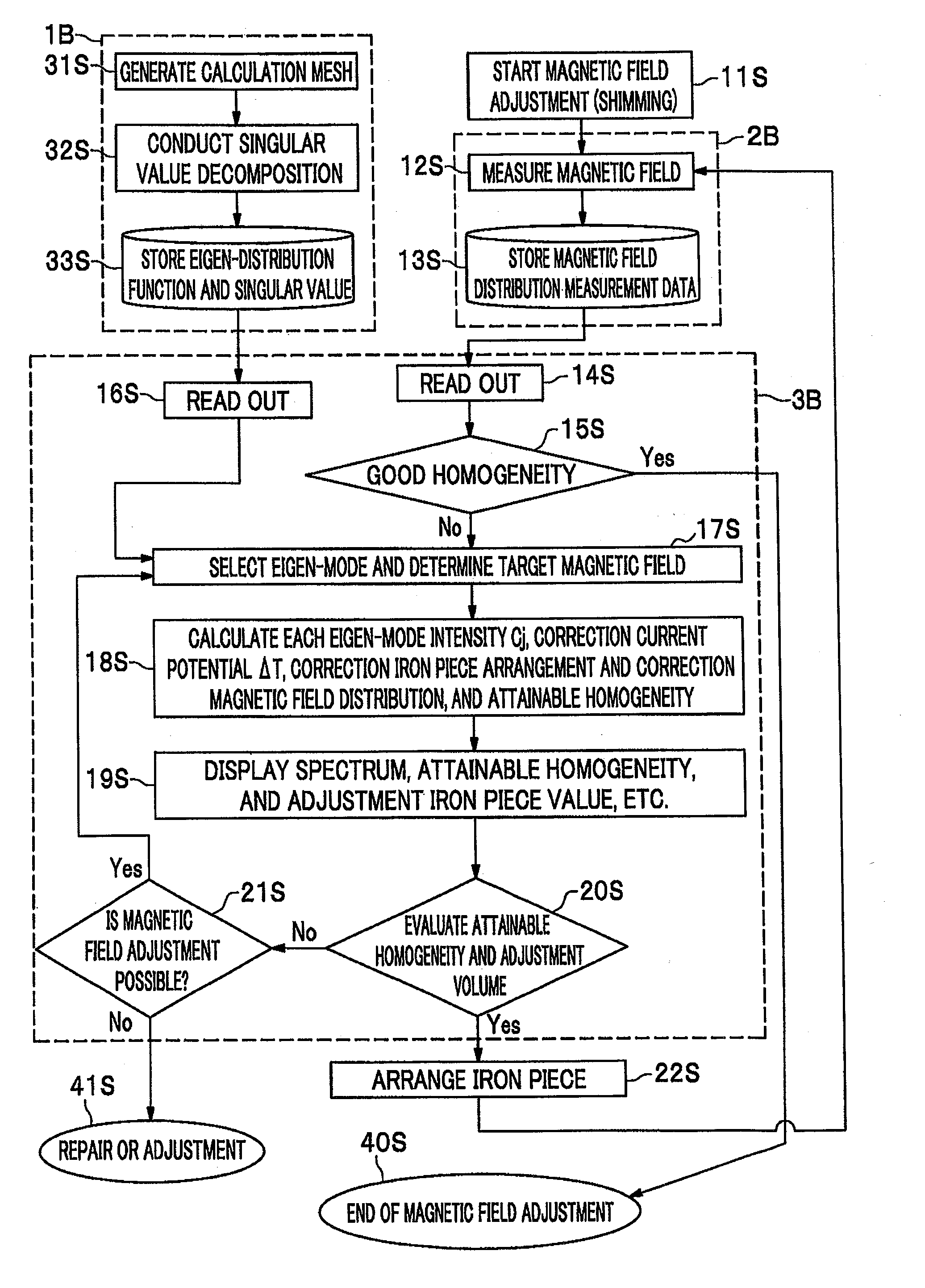
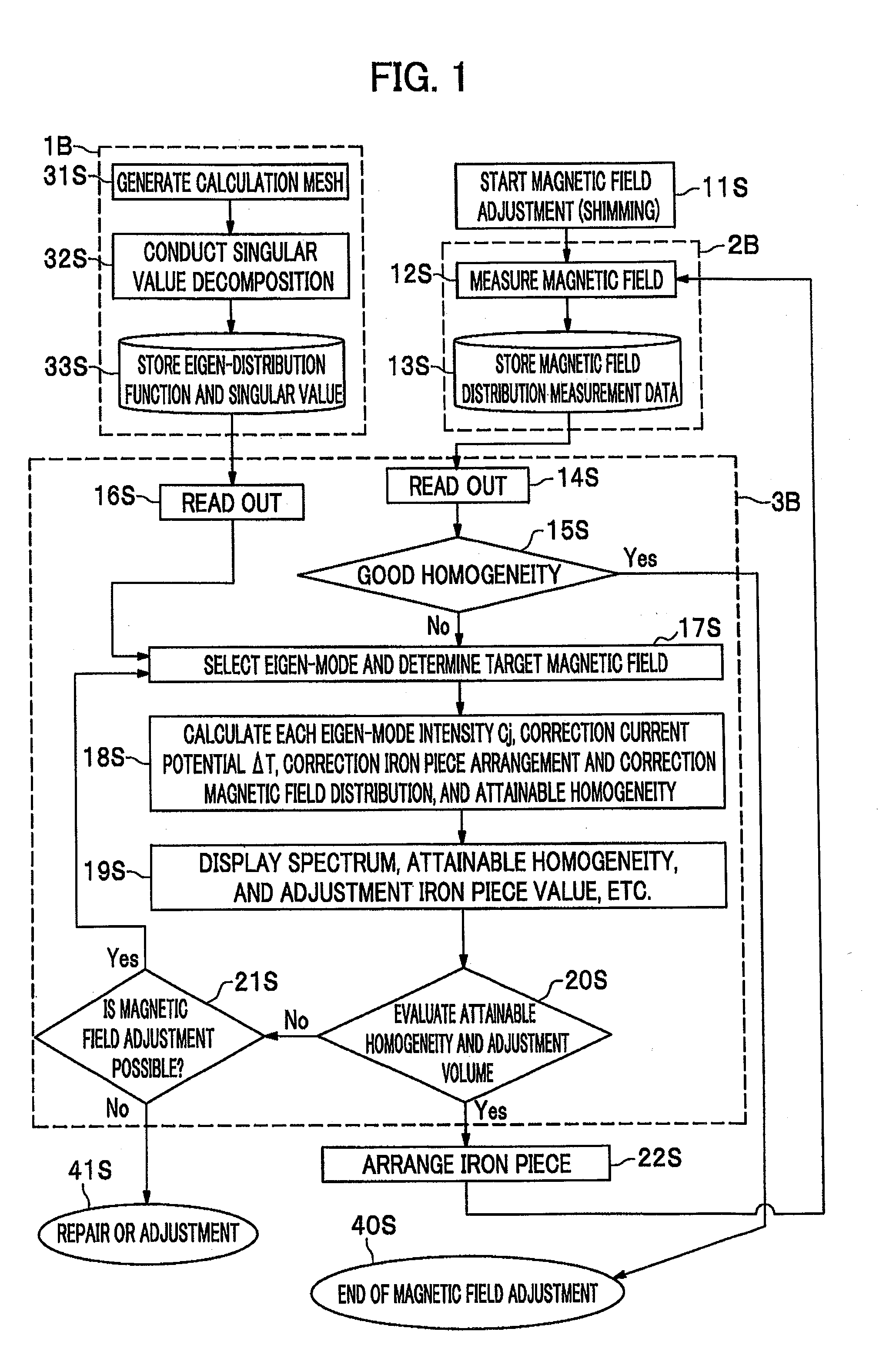
[0084]Will be described a first embodiment. Application to the magnetic field adjustment (shimming) in an open type MRI device having a vertical magnetic field will be described as the first embodiment. FIG. 5 shows a system of the magnetic field adjustment (shimming) for a magnetic field generated by a magnet of the MRI device in FIG. 5. This drawing is made with supposing an open type in which a direction of a magnetic field (line of magnetic force) is directed to a vertical direction. A conception shape of an open type MRI magnet is shown in a drawing of FIG. 5. There are magnet devices 62 divided in a vertical direction and connecting columns connects them therebetween.

[0085]Inside them, there are a vacuum vessel 62c for securing vacuum for thermal insulation, a radiation shield 62d, a cryogenic temperature vessel 62e, and coil groups 62a including a magnetic filed shielding coil 62b. A person to be inspected lies on the patient bed 61, and a nuclear magnetic resonance tomograph...

second embodiment

[0107]Will be described a second embodiment. It has been described previously that this method is usable for inspection of quality after manufacturing. However, this method is also usable for designing a magnet in accordance with the same determination. A flowchart of this case is shown in FIG. 10. In this embodiment, the magnetic adjustment is done through calculation, this method is applied to a magnetic force arrangement design by confirming that the target magnetic field accuracy can be reached. After a magnet motive force arrangement consideration start step 51S, a magnet motive force arrangement assuming step 52S is done. A magnetic field calculation step 53S is done on the basis of the magnet motive force arrangement. In addition, a singular value decomposition is done on the basis of the arrangement in the shimming tray from the magnet motive force arrangement, and the result is stored. This pre-calculation part 1B is the same as that of the first embodiment. The part 1B is ...

third embodiment

[0115]Because the calculation method and the process of the shimming can be performed also in the magnet device 62 for a vertical magnetic field type and the magnet device 62 for a horizontal magnetic field type through the same thinking, they are applicable to the magnetic field adjustment (shimming) for a horizontal magnetic field type MRI, a quality control, and the electric motive force arrangement design. However, because of difference in a shape of the magnet devices 62, there are different points in a calculating procedure and arrangement positions of the iron piece 4. Accordingly, this will be described as a third embodiment blow. In the third embodiment, this will be applied to the magnet device 62 for the horizontal magnetic field type MRI shown in FIG. 11. In this case, in a bore 62f (a hollow sleeve hole) penetrating a center part of the magnet device shown in FIG. 11, a region (the shim-tray 5) usable for shimming in a sleeve shape is arranged. A plane of the shim-tray ...


PUM


Abstract

An eigen-mode to be corrected is selected in accordance with an attainable magnetic field accuracy (homogeneity) and appropriateness of arranged volume of the iron pieces. Because the adjustment can be made with the attainable magnetic field accuracy (homogeneity) being grasped, an erroneous adjustment can be grasped, and the adjustment is automatically done during repeated adjustment. When the magnetic field adjustment is carried out with support by the method of the present invention according to the first and second embodiments or an apparatus including this method therein, the magnetic field adjustment can be surely completed. As a result, the apparatus with a high accuracy can be provided. In addition, there is an advantageous effect of earlier detection of a poor magnet by checking the attainable homogeneity. They are applicable to magnet devices for the horizontal magnetic field type, being an open type MRI, and vertical magnetic field type MRI.

Description

TECHNICAL FIELD[0001]The present invention relates to a superconducting magnet apparatus and a nuclear magnetic resonance tomographic apparatus (Magnetic Resonance Imaging).BACKGROUND ART[0002]In diagnosis using a nuclear magnetic resonance, a required accuracy in a magnetic intensity of the magnet system is such that variation of one millionth in magnetic intensity is considered to be a problem because a magnetic intensity corresponds to a diagnosis place. There are three types of magnetic fields in MRI devices. That is:(1) A magnetic field that is a constant in time base and uniform in space, and has an intensity of generally more than 0.1 to several teslas and a variation range of about several ppm within a space for imaging (a space of a sphere or an ellipsoid with a diameter of 30 to 40 cm);(2) A magnetic field varying with a time constant of about one second or shorter and inclined in a space; and(3) An electromagnetic wave caused by a high frequency wave having a frequency (s...

Claims


Application Information

Patent Timeline
IPC IPC(8): G01R33/44
CPCG01R33/3875G01R33/3873
Inventor ABE, MITSUSHIANDO, RYUYA
Owner HITACHI LTD
Why Eureka
Try Eureka