
Heat sink structures, lighting elements and lamps incorporating same, and methods of making same

a technology of heat sink and lighting elements, applied in the field of general illumination, can solve the problems of many solid-state light emitters not working as well as possible, and achieve the effects of good color rendering index, good contrast, and high efficiency

Active Publication Date: 2012-10-25
IDEAL IND LIGHTING LLC
View PDF27 Cites 160 Cited by
  • Summary
  • Abstract
  • Description
  • Claims
  • Application Information

AI Technical Summary

Benefits of technology

[0028]There is therefore a need for high efficiency solid-state light sources that combine the efficiency and long life of solid state light emitters with an acceptable color temperature and good color rendering index, good contrast, a wide gamut and / or simple control circuitry.
[0034]As noted above, the brightness of light emitted by many solid state light emitters, when supplied with a given current, can vary as a result of temperature change. The desire to maintain a relatively stable color of light output is therefore an important reason to try to reduce temperature variation of solid state light emitters.
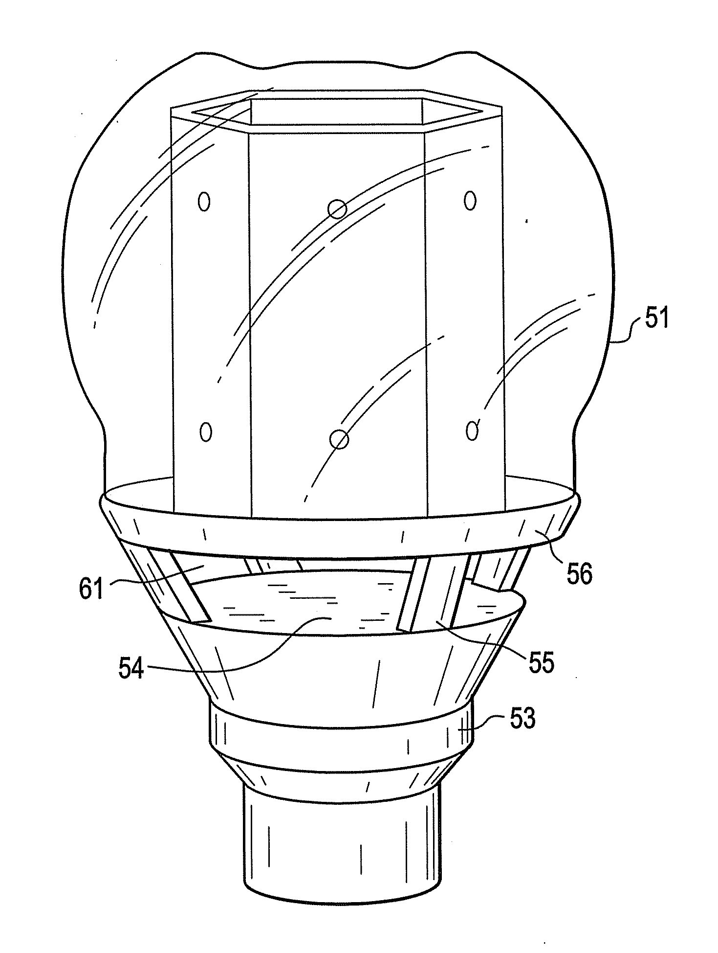
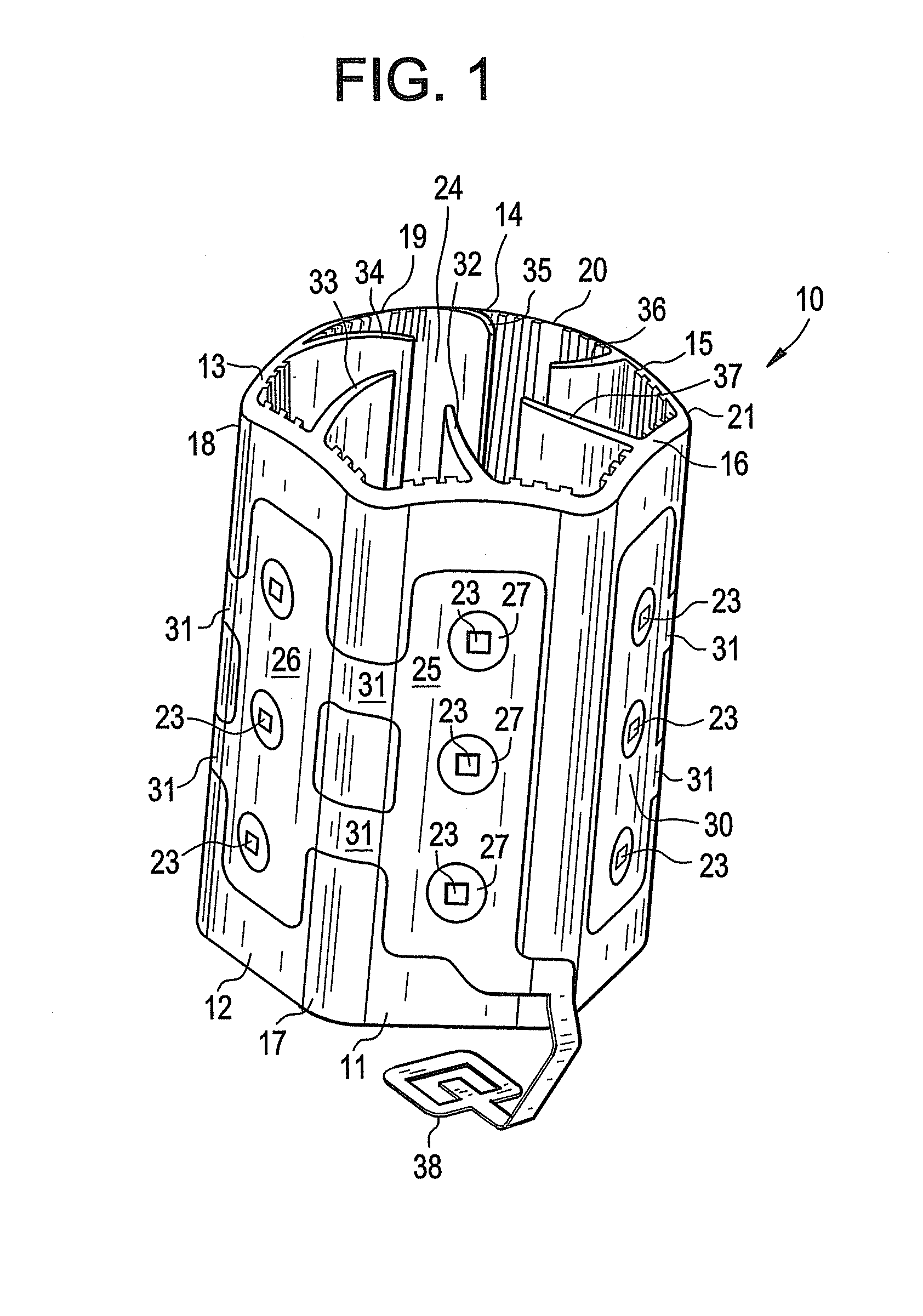
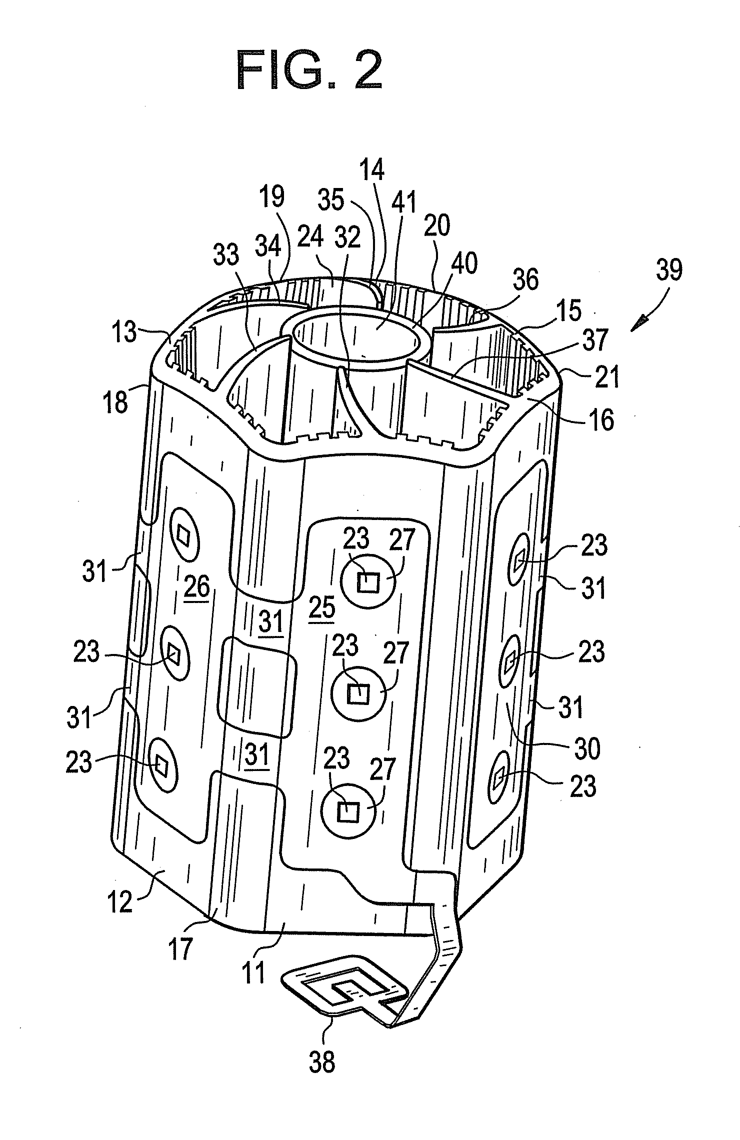
[0036]In some aspects of the present inventive subject matter, there is provided a lighting element (that can be used in making a lamp) that comprises a foldable (or folded) heat sink structure, a circuit board and a plurality of solid state light emitters, in which the heat sink structure comprises a plurality of heat sink regions (that together extend around an internal space) and optionally a plurality of heat dissipation elements (e.g., fin elements) that extend from the heat sink structure into the internal space, in which the circuit board is mounted on two or more of the heat sink regions, on surfaces opposite from surfaces that face the internal space, and in which the solid state light emitters are mounted on the circuit board (and on different heat sink regions, with portions of the circuit board intervening between the solid state light emitters and the respective heat sink regions), whereby ambient fluid (e.g., air) can travel through the internal space to assist in removing heat generated by the solid state light emitters and / or other components of the lighting element or lamp.
[0057]at least the second solid state light emitter is on the second heat sink region. The expression “fold region”, as used herein, means a region on a structure that is between first and second portions of the structure, the fold region being of rigidity that is lower than the rigidity of the first and second portions of the structure, whereby the first portion of the structure can be rotated about the fold region and relative to the second portion of the structure, with less force than would be required to rotate a first region of the first portion of the structure relative to a second region of the first portion of the structure about a line (which is not along a fold region) that is located between the first portion of the structure and the second region of the first portion of the structure. In some embodiments according to this aspect of the present inventive subject matter, (1) the first fold region is substantially linear and has a thickness that is less than a thickness of every portion of each of the first and second heat sink regions, (2) the first fold region comprises a hinge structure (e.g., the first heat sink region is rotatable, to some degree, relative to the second heat sink region and / or the first heat sink region has been rotated at least once, and in some cases many times, relative to the second heat sink region, and / or (3) the material stiffness of the heat sink structure is reduced, relative to other locations on the first heat sink region and on the second heat sink region, along the first fold region. In some embodiments according to this aspect of the present inventive subject matter, the first heat sink structure can comprise one or more heat dissipation elements (e.g., one or more fin elements) attached to the first heat sink region. In some embodiments according to this aspect of the present inventive subject matter, the lighting element can further comprise at least a first circuit board that extends across the first fold region.

Problems solved by technology

A challenge with solid state light emitters is that many solid state light emitters do not operate as well as possible when they are subjected to elevated temperatures.

Method used


Image

  • Heat sink structures, lighting elements and lamps incorporating same, and methods of making same
  • Heat sink structures, lighting elements and lamps incorporating same, and methods of making same
  • Heat sink structures, lighting elements and lamps incorporating same, and methods of making same

Examples


Embodiment Construction

[0154]The present inventive subject matter now will be described more fully with reference to the accompanying drawings, in which embodiments of the inventive subject matter are shown. However, this inventive subject matter should not be construed as being limited to the embodiments set forth herein. Rather, these embodiments are provided so that this disclosure will be thorough and complete, and will fully convey the scope of the inventive subject matter to those skilled in the art. Like numbers refer to like elements throughout.

[0155]As used herein the term “and / or” includes any and all combinations of one or more of the associated listed items. All numerical quantities described herein are approximate and should not be deemed to be exact unless so stated.

[0156]The terminology used herein is for the purpose of describing particular embodiments only and is not intended to be limiting of the inventive subject matter. As used herein, the singular forms “a”, “an” and “the” are intende...


PUM

PropertyMeasurementUnit
Angleaaaaaaaaaa
Thicknessaaaaaaaaaa
Poweraaaaaaaaaa

Abstract

In some embodiments, a lighting element comprising at least first and second solid state light emitters, a first heat sink structure with a fold region between first and second heat sink regions, and at least one light emitter on each of the heat sink regions, and methods of making. In some embodiments, a lighting element, comprising plural heat sink regions on respective regions of a flexible circuit board, and plural light emitters on respective regions of the flexible circuit board, and methods of making. In some embodiments, heat sink structures comprising plural heat sink regions and a circuit board with plural regions, and lighting elements comprising them. In some embodiments, a heat sink structure, comprising plural heat sink regions and an internal flow guide structure, and lighting elements comprising same. Also, other lighting elements, lamps and heat sink structures.

Description

FIELD OF THE INVENTIVE SUBJECT MATTER[0001]The inventive subject matter relates to the field of general illumination. In some aspects, the inventive subject matter relates to a lamp (and components for such a lamp) that comprises one or more solid state light emitters and that can be connected to a standard electrical connector, e.g., an electrical connector that is conventionally used for installing an incandescent lamp, a fluorescent lamp or any other type of lamp, such as an Edison socket or a GU-24 socket, for example. In some aspects, the inventive subject matter relates to such a lamp (and components for such a lamp) that is of a size and / or shape that is relatively close to a size and / or shape of a conventional lamp. In some aspects, the inventive subject matter relates to a lamp (and components for such a lamp) that can provide high efficiency and good CRI Ra over long lamp lifetimes.BACKGROUND[0002]There is an ongoing effort to develop systems that are more energy-efficient...

Claims


Application Information

Patent Timeline
IPC IPC(8): F21S4/00F28F7/00B21D53/02F21V29/00
CPCF21K9/135Y10T29/4935F21V23/02F21Y2101/02F21Y2111/005H05K3/284H05K2201/10106F21V3/02F21V29/20F21V29/506F21V29/74F21V29/75F21V29/777F21V29/78F21V29/80F21V29/83F21V29/85F21K9/90F21K9/00F21K9/232F21Y2107/30F21Y2115/10
Inventor PICKARD, PAUL KENNETHPROGL, CURTGRAY, JOSHUA N.
Owner IDEAL IND LIGHTING LLC
Learn More