Corium cooling structure, reactor containment vessel provided with the same, and nuclear power plant provided with the same

a technology of corium and containment vessel, which is applied in the direction of nuclear power plants, climate sustainability, greenhouse gas reduction, etc., can solve the problems of corium destruction of reactor vessels, and achieve the effect of enhancing cooling efficiency

Inactive Publication Date: 2012-10-25
MITSUBISHI HEAVY IND LTD
View PDF3 Cites 17 Cited by
  • Summary
  • Abstract
  • Description
  • Claims
  • Application Information

AI Technical Summary

Benefits of technology

[0028]The corium cooling structure is provided with a capture portion and a plurality of pipe portions into which corium that has flowed out from a reactor flows via the capture portion. In addition, the plurality of pipe portions are provided inside a coolant storing portion. Because of this, the corium can be dispersed into a plurality of small divided portions to be accumulated in the pipe portions. Therefore, the corium that has flowed out can be prevented from accumulating in a pile.
[0029]In addition, contact areas between the small divided portions of corium that has flowed into the pipe portions and coolant in the coolant storing portion can be increased by means of the pipe portions. Therefore, the cooling efficiency can be enhanced for the corium that has flowed out from the reactor.

Problems solved by technology

However, in the event of failure of the emergency reactor-core cooling apparatus, the reactor core cannot be cooled, causing the reactor core to melt down, and thus, the reactor vessel is destroyed by corium, such as melted fuel, etc.

Method used


Image

  • Corium cooling structure, reactor containment vessel provided with the same, and nuclear power plant provided with the same
  • Corium cooling structure, reactor containment vessel provided with the same, and nuclear power plant provided with the same
  • Corium cooling structure, reactor containment vessel provided with the same, and nuclear power plant provided with the same

Examples


first embodiment

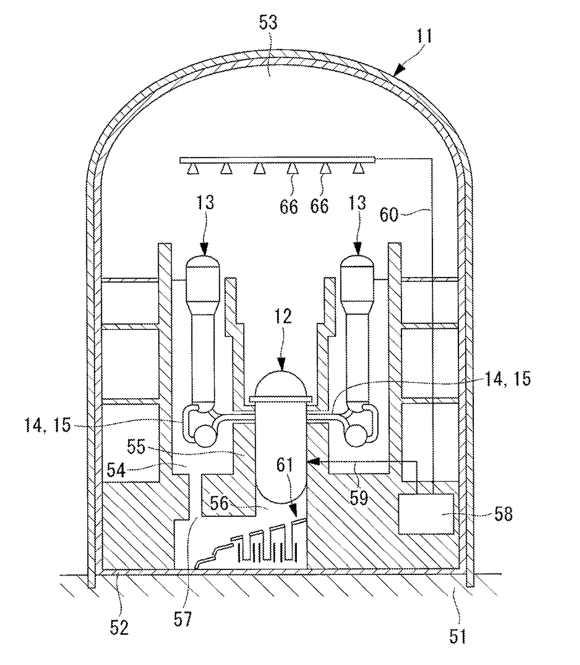
[0034]FIG. 1 shows, in outline, a configuration diagram of a reactor containment vessel of a nuclear power plant having a corium cooling structure according to a first embodiment of the present invention.

[0035]A reactor containment vessel 11 of a nuclear plant (not shown) accommodates a pressurized water reactor (reactor) 1 and steam generators 13, and the pressurized water reactor 12 and the steam generators 13 are connected via cooling-fluid pipes 14 and 15. The cooling-fluid pipes 14 are provided with pressurizers (not shown), and the cooling-fluid pipes 15 are provided with cooling-fluid pumps (not shown).

[0036]Light water is used as a moderator and as primary cooling fluid, and, in order to suppress boiling of the primary cooling fluid in the reactor core of the pressurized water reactor 12, the primary cooling fluid system is controlled by the pressurizer so that a high-pressure state of about 160 atm is maintained. Accordingly, the light water, serving as the primary cooling ...

second embodiment

[0082]A second embodiment of the present invention will be described below. A corium cooling structure of this embodiment and a reactor containment vessel provided with the same differ from those in the first embodiment in that the pipe portions are provided in the entire region of the inclined plate; however, other components are similar. Therefore, with regard to the same configuration and the same flow, the same reference signs are assigned and descriptions thereof will be omitted.

[0083]FIG. 4 shows, in outline, a configuration diagram of a corium cooling structure according to the second embodiment of the present invention.

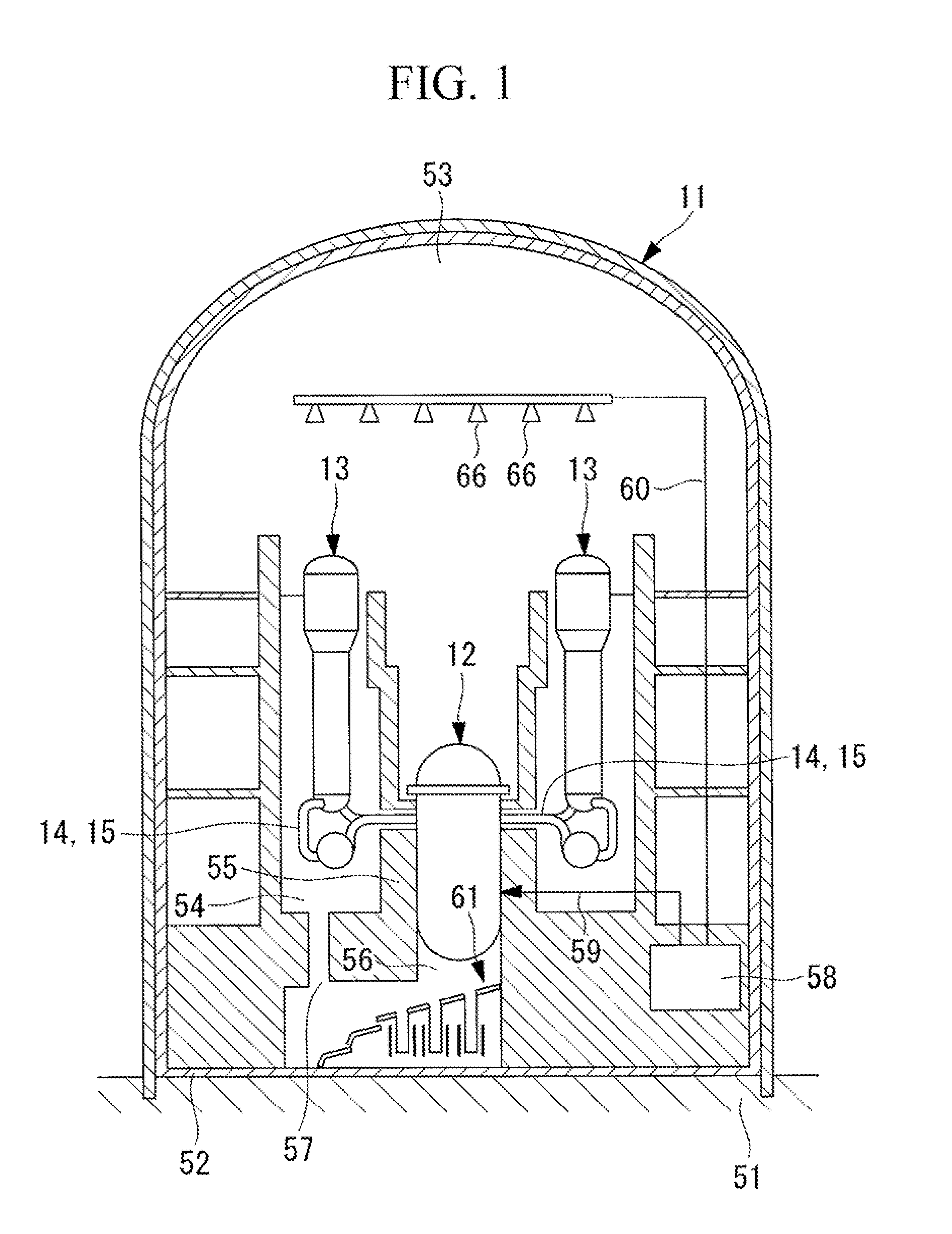
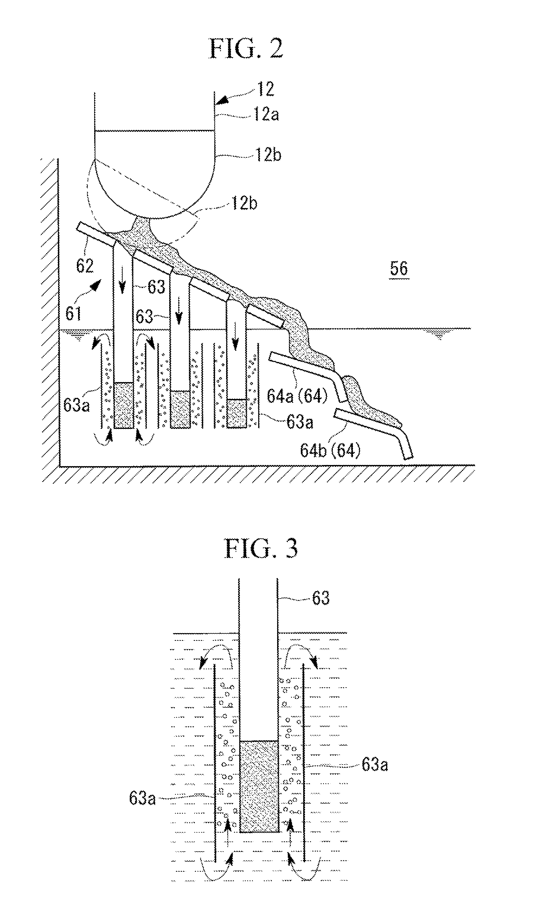
[0084]The plurality of pipe portions 63 are provided in the entire region of the inclined plate (capture portion) 62 in the core catcher (corium cooling structure) 61. The distal end side (start-point side of the slope) of the inclined plate 62 is submerged in the cooling fluid (coolant) stores in the cavity (cooling maintaining portion) 56.

[0085]As described ...


PUM


Abstract

An object is to provide a corium cooling structure that is capable of accumulating corium and debris that have flowed out from a reactor in small divided portions and of sufficiently cooling the high-temperature corium and debris, a reactor containment vessel provided with the same, and a nuclear power plant provided with the same. A capture portion that captures the corium that has flowed out from a reactor and a plurality of pipe portions that are provided in a coolant storing portion and into which the corium flows via the capture portion are provided.

Description

TECHNICAL FIELD [0001]The present invention relates to a corium cooling structure, a reactor containment vessel provided with the same, and a nuclear power plant provided with the same, and, in particular, relates to cooling of corium that has flowed out from a reactor.BACKGROUND ART [0002]Generally in a pressurized water reactor (PWR: Pressurized Water Reactor), a reactor core inside a reactor vessel is cooled by an emergency reactor-core cooling apparatus, which is activated when a loss-of-coolant accident (LOCA: Loss of Coolant Accident) or a transient phenomenon (transient) occurs. However, in the event of failure of the emergency reactor-core cooling apparatus, the reactor core cannot be cooled, causing the reactor core to melt down, and thus, the reactor vessel is destroyed by corium, such as melted fuel, etc. The corium that has destroyed the reactor vessel penetrates a bottom portion of the reactor vessel, drops into a cavity in which coolant is stored, and is cooled therein...

Claims


Application Information

Patent Timeline
Patent Type & Authority Applications(United States)
IPC IPC(8): G21C9/016
CPCY02E30/40G21C9/016Y02E30/30
Inventor KONDO, YOSHIYUKISUZUTA, TADAHIKOYAMAGISHI, MAKOTOGODA, HIROSHITANIMOTO, KOICHI
Owner MITSUBISHI HEAVY IND LTD
Why Eureka
Try Eureka