Apparatus and method for treating myofascial trigger points

a trigger point and myofascial technology, applied in the field of myofascial trigger point apparatus and method, can solve the problems of restricted blood flow (ischemia) through the muscle in the vicinity, pain and immobility, and blood flow restriction, and achieve optimal pressure, enhance the treatment of myofascial trigger points, and prevent the patient's tense response

Inactive Publication Date: 2012-10-25
CLIPPER PROFESSIONAL MEDICAL SERVICES
View PDF4 Cites 22 Cited by
  • Summary
  • Abstract
  • Description
  • Claims
  • Application Information

AI Technical Summary

Benefits of technology

[0010]The present invention is a device and related method for the delivery, including the optional self-delivery, of trigger point pressure. The device and method enable selective application of trigger point pressure, which pressure may be gradual, uniform and systematic but is not limited thereto. The device and method enable the application of trigger point pressure in a manner that allows a patient to tolerate the applied pressure without tensing the relevant muscles and without causing the trigger point to become hyperirritable. The device and method also enable the gradual selectable increase in that applied pressure while still preventing the tense response from the patient so that the optimal pressure is achieved. The device enabl

Problems solved by technology

Trigger points can be latent, causing stiffness, posture distortion, and motion restriction, or active, causing pain and immobility.
This issue is most common among middle-aged adults and can result from many different causes including, but not limited to, muscle strains, stress, overuse, trauma, and poor nutrition.
Trigger points result in restricted blood flow (ischemia) through the muscle in that vicinity of the trigger point.
That blood flow restriction produces significant pain, restricted motion and disability in a person.
Unfortunately, many patients do not respond well to current treatment mechanisms.
As a result, long-term symptoms have not been sufficiently addressed for a sufficient number of people.
Unfortunately, this process of increased pressure application generally occurs all within the same session and is therefore not well associated with the particular patient's condition and needs.
However, current massage treatment can be less than optimal due to a lack of, or excessive, intensity.
Further, some trigger points are located in places that are too difficult to thoroughly massage.
Also, suitably reliable pressure may not always be applied to the right location for a sufficient period of time.
Massage treatment may also be too expensive for some patients to rely upon for a sufficient length of time to address adequately the myo

Method used


Image

  • Apparatus and method for treating myofascial trigger points
  • Apparatus and method for treating myofascial trigger points
  • Apparatus and method for treating myofascial trigger points

Examples


first embodiment

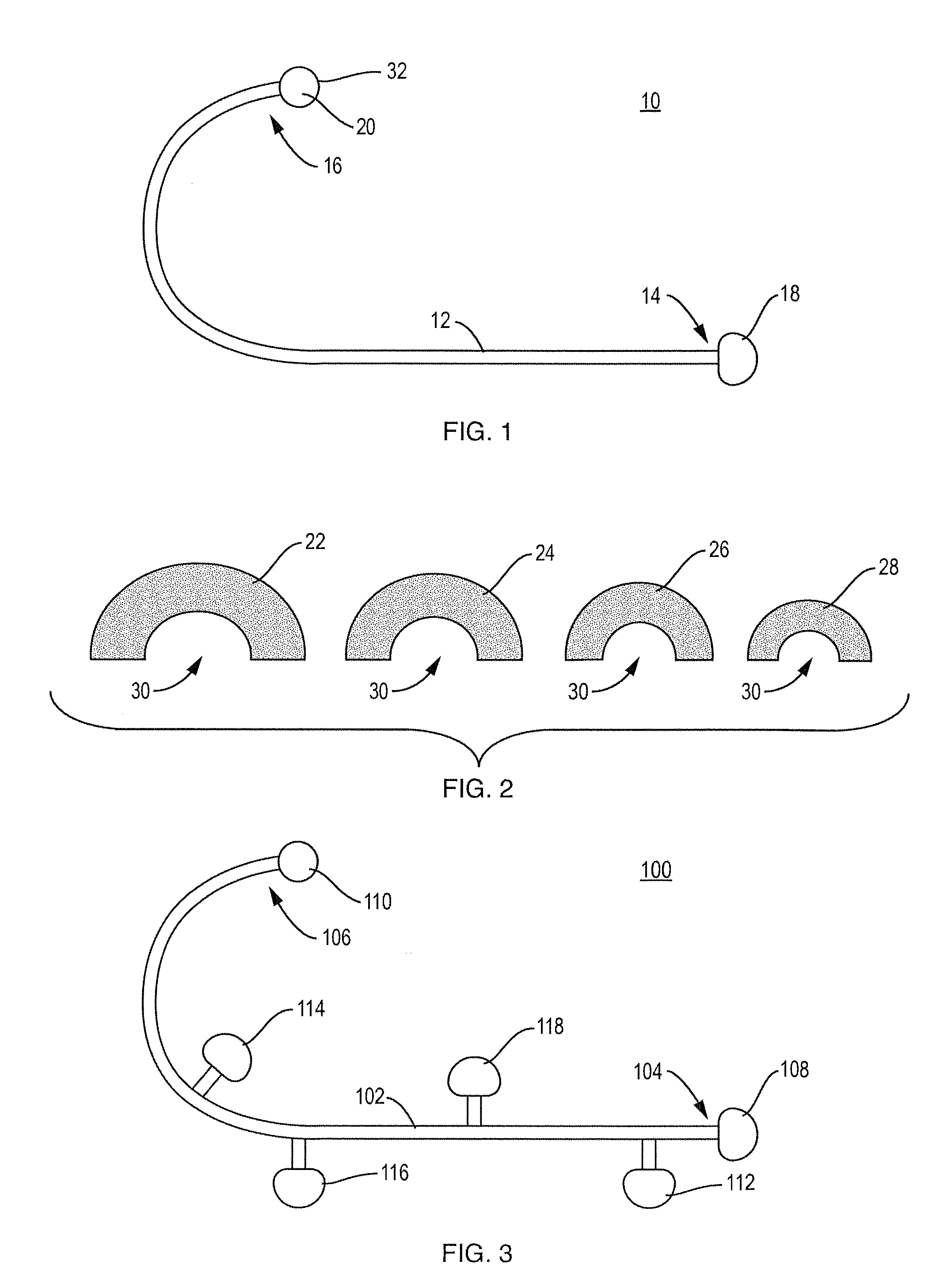
[0022]The present invention is a massage device and method for the self treatment of myofascial pain and one or more associated trigger points. While this description of the preferred embodiment of the invention is directed to the treatment of trigger points, it is to be understood that is equally applicable to the treatment of any sort of muscle pain, muscle tightness or any other condition for which the application and release of pressure in a gradual, progressive and / or selectable way is considered to be beneficial. a massage device 10 is shown in FIG. 1. The device 10 includes a primary body 12 with a first end 14 and a second end 16. The first end 14 includes a knob 18 that a patient may hold onto when employing the device 10. The second end 16 includes a terminal base 20. The terminal base 20 is shown as rounded but is not limited to that shape. The device 10 may be formed as one or more pieces and may be fabricated of a metal material or a non-metallic material including, but...

second embodiment

[0028]the invention is shown in FIG. 3. A second massage device 100 includes a primary body 102 with a first end 104 and a second end 106. The first end 104 includes a knob 108 that a patient may hold onto when employing the device 100. The second end 106 includes a terminal base 110. The primary body 102 also includes a plurality of pressure bases, a first pressure base 112, a second pressure base 114, a third pressure base 116 and a fourth pressure base 118. Each of the terminal base 110 and the pressure bases is shown as rounded but they are not limited to that shape. The device 100 may be formed as one or more pieces and may be fabricated of a metal material or a non-metallic material including, but not limited to, a viscoelastic material. The primary body 102 of the device 100 is shown in a curved arrangement to facilitate a user's application of the terminal base 110 and one or more of the pressure bases to the user's back by pressing on the knob 108. In that respect, the devi...

third embodiment

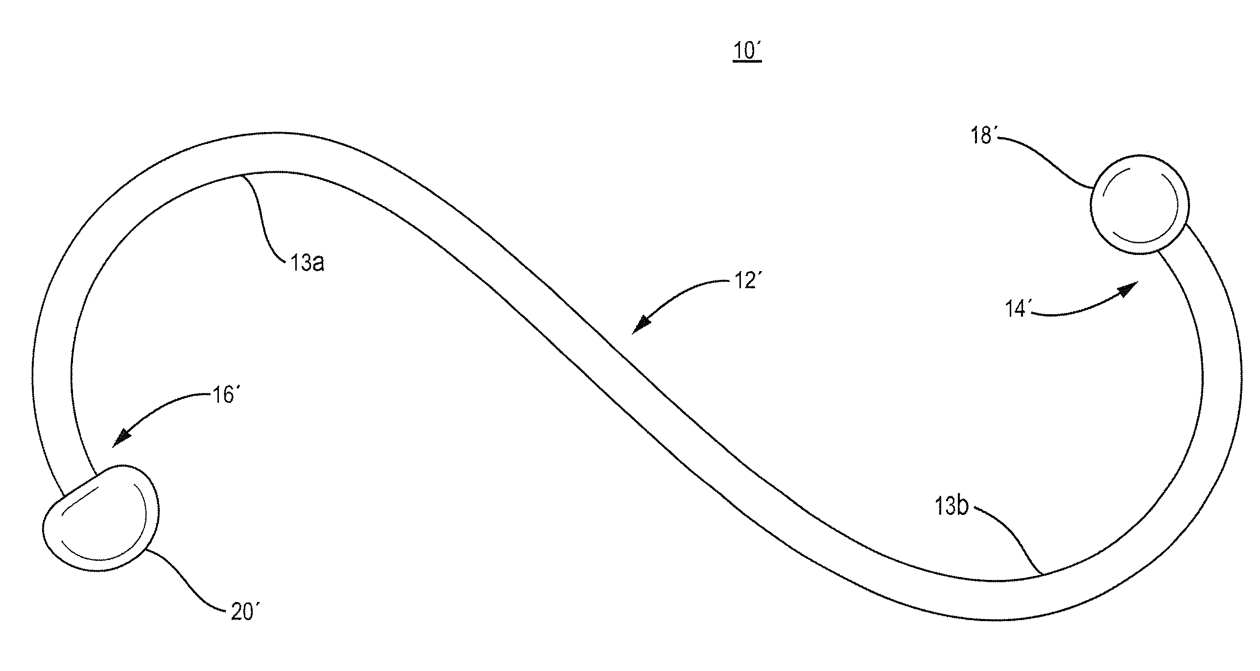
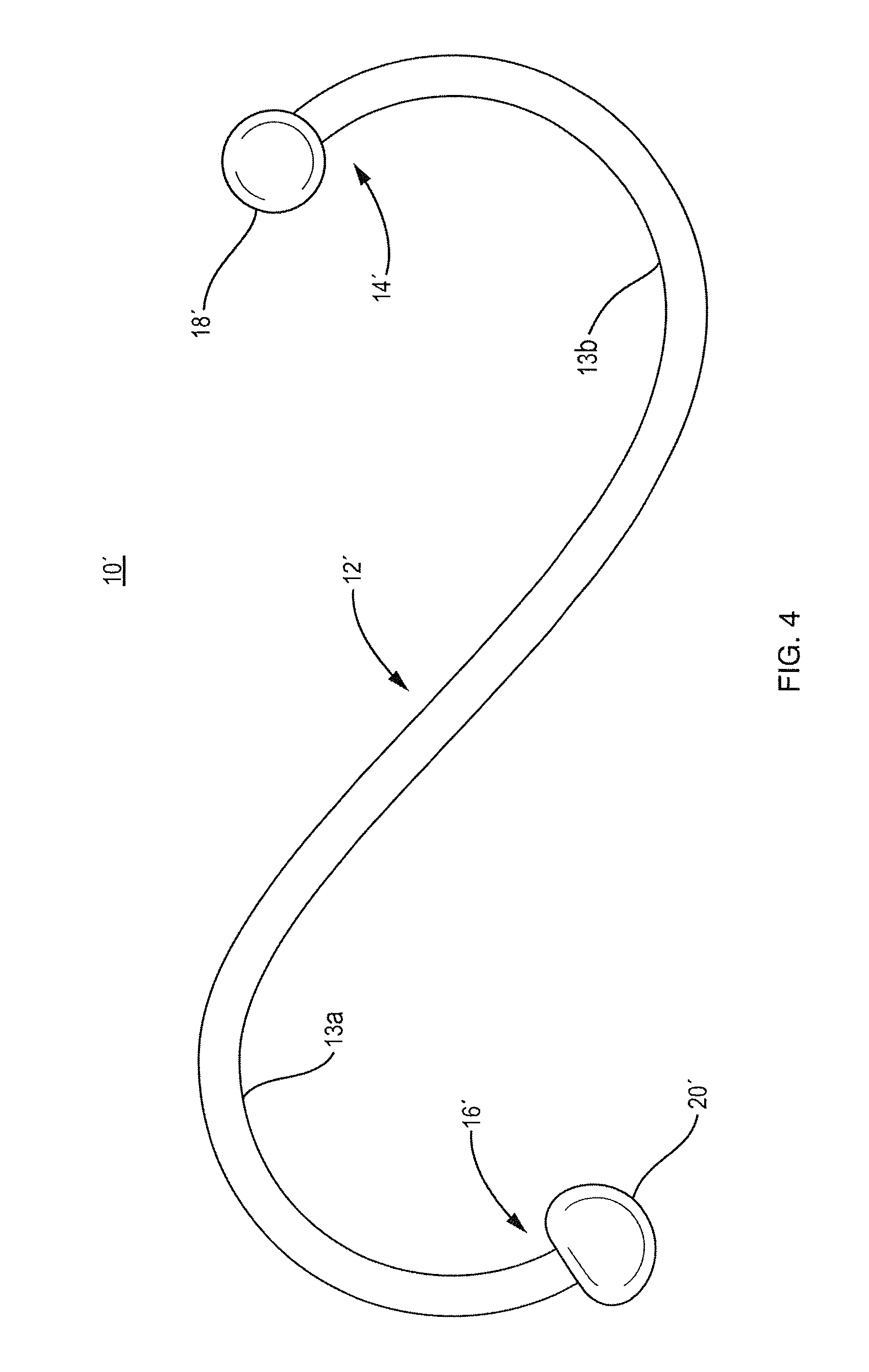
[0031]a massage device 10′ is shown in FIG. 4. The device 10 includes a primary body 12′ with a first end 14′ and a second end 16′. The first end 14′ includes a knob 18′ that a patient may hold onto when employing the device 10′. The second end 16′ includes a terminal base 20′. The terminal base 20′ is shown as rounded but is not limited to that shape. The device 10′ may be formed as one or more pieces and may be fabricated of a metal material or a non-metallic material including, but not limited to, a viscoelastic material. The primary body 12′ of the device 10′ is shown in a double curved arrangement to facilitate a user's application of the terminal base 20′ to the user's back by hooking first curve 13a over the shoulder and pressing on second curve 13b and / or pressing on the knob 18′. In that respect, the device 10 shown is similarly shaped to the Backnobber™ II product described above modified to include the end caps described herein removably applied to the terminal base 20′.

[...


PUM


Abstract

A device and method for the application of pressure to a location where muscle pain exists, including at a trigger point. The device and method provide gradual, uniform and systematic progression of pressure and release. The device and method enable the application of pressure in a manner that allows a patient to tolerate the pressure without tensing the relevant muscles and/or causing the locus of pain to become hyperirritable and painful. The device and method also enable the gradual selectable increase in that applied pressure while still preventing the tense response from the patient so that the optimal or desired amount of focused pressure is tolerated. The device enables progressive deep tissue massage in systematic and progressive steps that enhances the treatment of myofascial trigger points in skeletal muscles and other forms of muscle pain. The device includes a plurality of terminal configurations that differ in hardness and/or dimensions.

Description

CROSS REFERENCE TO RELATED APPLICATION[0001]This application claims the priority benefit of U.S. provisional application Ser. No. 61 / 478,178 filed Apr. 22, 2011, entitled APPARATUS AND METHOD FOR TREATING MYOFASCIAL TRIGGER POINTS, of the same named inventor. The entire content of the priority application is incorporated herein by reference.FIELD OF THE INVENTION[0002]The present invention relates generally to an apparatus and method for treating myofascial trigger points. More specifically, the apparatus is configured to enable a patient to self-treat myofascial trigger points through the progressive application of different pressures to the trigger points through massage and / or trigger point pressure and release of that pressure. The related method provides particular steps associated with the use of the apparatus.BACKGROUND OF THE INVENTION[0003]The fibrous tissue that encloses and separates muscle layers is identified as myofascial tissue. A myofascial trigger point is a hyper-i...

Claims


Application Information

Patent Timeline
IPC IPC(8): A61B17/00
CPCA61H2201/0153A61H7/001A61H39/04A61H2201/169A61H2201/1253A61H2201/168A61H2201/1685A61H2201/0157
Inventor TORRES, JONATHAN K.
Owner CLIPPER PROFESSIONAL MEDICAL SERVICES
Why Eureka
Try Eureka