Audio signal encoder, audio signal decoder, method for encoding or decoding an audio signal using an aliasing-cancellation

Active Publication Date: 2012-10-25
FRAUNHOFER GESELLSCHAFT ZUR FOERDERUNG DER ANGEWANDTEN FORSCHUNG EV +3
View PDF8 Cites 118 Cited by
  • Summary
  • Abstract
  • Description
  • Claims
  • Application Information

AI Technical Summary

Benefits of technology

[0028]In an embodiment, the audio signal decoder is configured to combine a windowed and folded version of at least a portion of a time-domain representation obtained using the ACELP mode with a time-domain representation of a subsequent portion of the audio content obtained using the TCX-LPD mode, to at least partially cancel an aliasing. It has been found that the usage of such aliasing-cancellation mechanisms, in addition to the generation of the aliasing cancellation synthesis signal, provides the possibility of obtaining an aliasing-cancellation in a very bitrate efficient manner. In particular, the necessitated aliasing-cancellation stimulus signal can be encoded with high efficiency if the aliasing-cancellation synthesis signal is supported, in the aliasing-cancellation, by the windowed and folded version of at least a portion of a time-domain representation obtained using the ACELP mode.
[0029]In an embodiment, the audio signal decoder is configured to combine a windowed version of a zero impulse response of the synthesis filter of the ACELP branch with a time-domain representation of a subsequent portion of the audio content obtained using the TCX-LPD mode, to at least partially cancel an aliasing. It has been found that the usage of such a zero impulse response may also help to improve the coding efficiency of the aliasing-cancellation stimulus signal, because the zero impulse response of the synthesis filter of the ACELP branch typically cancels at least a part of the aliasing in the TCX-LPD-encoded portion of the audio content. Accordingly, the energy of the aliasing-cancellation synthesis signal is reduced, which, in turn, results in a reduction of the energy of the aliasing-cancellation stimulus signal. However, encoding signals with a smaller energy is typically possible with reduced bitrate requirements.
[0030]In an embodiment, the audio signal decoder is configured to switch between a TCX-LPD mode, in which a capped frequency-domain-to-time-domain transform is used, a frequency-domain mode, in which a tapped frequency-domain-to time-domain transform is used, as well as an algebraic-code-excited-linear-prediction mode. In this case, the audio signal decoder is configured to at least partially cancel an aliasing at a transition between a portion of the audio content encoded in the TCX-LPD mode and a portion of the audio content encoded in the frequency-domain mode by performing an overlap-and-add operation between time domain samples of subsequent overlapping portions of the audio content. Also, the audio signal decoder is configured to at least partially cancel an aliasing at a transition between a portion of the audio content encoded in the TCX-LPD mode and a portion of the audio content encoded in the ACELP mode using the aliasing-cancellation synthesis signal. It has been found that the audio signal decoder also is well-suited for switching between different modes of operation, wherein the aliasing cancels very efficiently.
[0031]In an embodiment, the audio signal decoder is

Problems solved by technology

Moreover, it has been found that the performance of frequency-domain based audio coders is not optimal for audio contents comprising speech.
However,

Method used


Image

  • Audio signal encoder, audio signal decoder, method for encoding or decoding an audio signal using an aliasing-cancellation
  • Audio signal encoder, audio signal decoder, method for encoding or decoding an audio signal using an aliasing-cancellation
  • Audio signal encoder, audio signal decoder, method for encoding or decoding an audio signal using an aliasing-cancellation

Examples


Embodiment Construction

1. Audio Signal Decoder According to FIG. 1

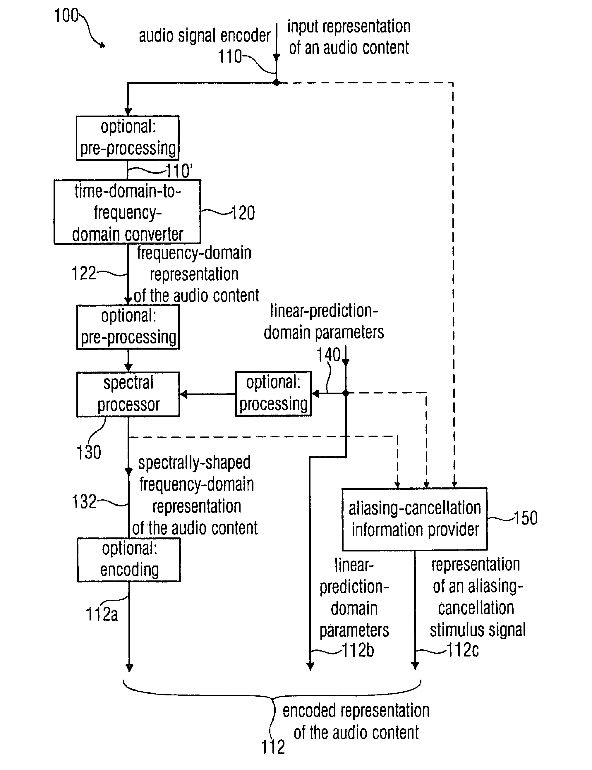
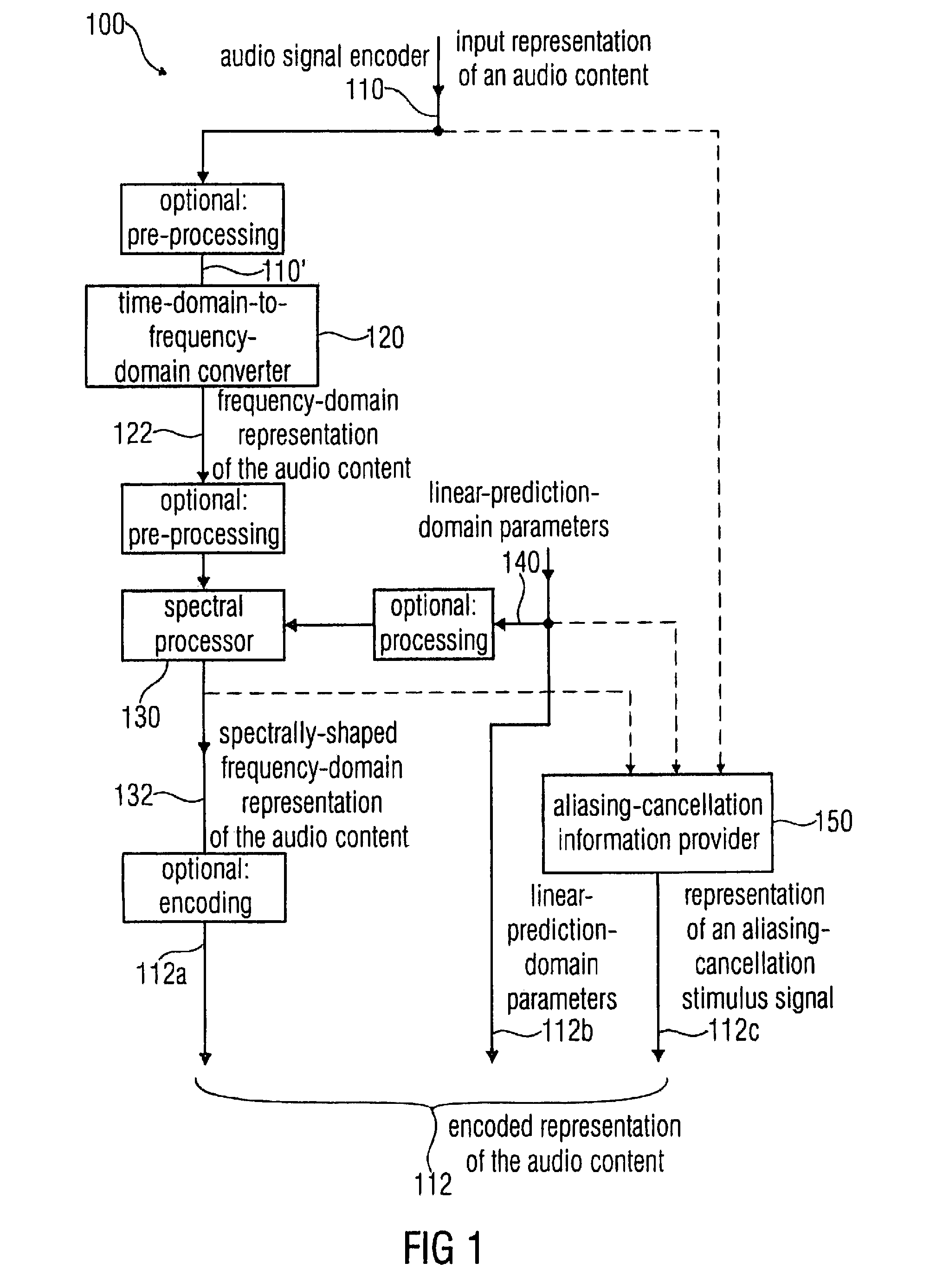
[0062]FIG. 1 shows a block schematic diagram of an audio signal encoder 100, according to an embodiment of the invention. The audio signal encoder 100 is configured to receive an input representation 110 of an audio content and to provide, on the basis thereof, an encoded representation 112 of the audio content. The encoded representation 112 of the audio content comprises a first set 112a of spectral coefficients, a plurality of linear-prediction-domain parameters 112b and a representation 112c of an aliasing-cancellation stimulus signal.

[0063]The audio signal encoder 100 comprises a time-domain-to-frequency-domain converter 120 which is configured to process the input representation 110 of the audio content (or, equivalently, a pre-processed version 110′ thereof), to obtain a frequency-domain representation 122 of the audio content (which may take the form of a set of spectral coefficients).

[0064]The audio signal encoder 100 also comprise...


PUM


Abstract

An audio signal decoder includes a transform domain path configured to obtain a time-domain representation of a portion of an audio content on the basis of a first set of spectral coefficients, a representation of an aliasing-cancellation stimulus signal and a plurality of linear-prediction-domain parameters. The transform domain path applies a spectrum shaping to the first set of spectral coefficients to obtain a spectrally-shaped version thereof. The transform domain path obtains a time-domain representation of the audio content on the basis of the spectrally-shaped version of the first set of spectral coefficients. The transform domain path includes an aliasing-cancellation stimulus filter to filter the aliasing-cancellation stimulus signal in dependence on at least a subset of the linear-prediction-domain parameters. The transform domain path also includes a combiner configured to combine the time-domain representation of the audio content with an aliasing-cancellation synthesis signal to obtain an aliasing reduced time-domain signal.

Description

CROSS-REFERENCE TO RELATED APPLICATIONS[0001]This application is a continuation of copending International Application No. PCT / EP2010 / 065752, filed Oct. 19, 2010, which is incorporated herein by reference in its entirety, and additionally claims priority from U.S. Application No. 61 / 253,468, filed Oct. 20, 2009, which is also incorporated herein by reference in its entirety.BACKGROUND OF THE INVENTION[0002]Embodiments according to the invention create an audio signal decoder for providing a decoded representation of an audio content on the basis of an encoded representation of the audio content.[0003]Embodiments according to the invention create an audio signal encoder for providing an encoded representation of an audio content comprising a first set of spectral coefficients, a representation of an aliasing-cancellation stimulus signal and a plurality of linear-prediction-domain parameters on the basis of an input representation of the audio content.[0004]Embodiments according to th...

Claims


Application Information

Patent Timeline
IPC IPC(8): G10L19/12G10L19/02G10L19/03G10L19/20
CPCG10L19/0212G10L19/20G10L19/03G10L2019/0008G10L19/00
Inventor BESSETTE, BRUNONEUENDORF, MAXGEIGER, RALFGOURNAY, PHILIPPELEFEBVRE, ROCHGRILL, BERNHARDLECOMTE, JEREMIEBAYER, STEFANRETTELBACH, NIKOLAUSVILLEMOES, LARSSALAMI, REDWANDEN BRINKER, ALBERTUS C.
Owner FRAUNHOFER GESELLSCHAFT ZUR FOERDERUNG DER ANGEWANDTEN FORSCHUNG EV
Why Eureka
Try Eureka