Evaporative pattern casting process

a technology of evaporative pattern and casting process, which is applied in the direction of foundry patterns, manufacturing tools, and moulding apparatus, etc., can solve the problems of increased processing cost, decreased workability, and complicated step of forming through holes in patterns, and achieves accurate setting, high precision, and superior quality

Active Publication Date: 2012-11-01
HONDA MOTOR CO LTD
View PDF1 Cites 5 Cited by
  • Summary
  • Abstract
  • Description
  • Claims
  • Application Information

AI Technical Summary

Benefits of technology

[0027]According to the invention recited in one of claims 1 to 4, the casting time during founding is set according to the modulus of the pattern. Therefore, the casting time in the evaporative pattern casting process is accurately set with high precision, whereby a casting product having superior quality is obtained.
[0028]In addition, according to the invention recited in one of claims 5 to 8, the gate is positioned at the level of the center of gravity of the product or at the level of the vicinity of the center of gravity of the product. Therefore, molten metal at high temperature is filled into the entire area of the pattern without increasing the number of the gates, whereby residue defects are effectively reduced.
[0029]Moreover, according to the invention recited in claim 9, blowback of the molten metal from the sprue is reliably prevented by an easy method that does not increase the production steps and the costs. Therefore, the casting process is safely performed. In addition, the rate of pouring the molten metal is increased as much as possible while the blowback is prevented. Therefore, the molten metal is rapidly poured, and the temperature of the molten metal that is poured last is maintained high. As a result, a casting product having high quality with little residue is obtained.
[0030]Furthermore, according to the invention recited in claim 10, the hollow space for discharging combustion gas is provided in the mold and has an upper end at the level of not more than the uppermost portion of the pattern. Therefore, it is not necessary to increase the head pressure by increasing the sprue height, and the casting is performed at minimum head pressure. As a result, the sprue height is reduced as much as possible, whereby increase of the casting production cost is prevented.

Problems solved by technology

Therefore, steps of forming a mold and steps of cutting the gates for obtaining a product after the casting are increased, whereby the workability is decreased, and the processing cost is increased.
In the technique disclosed in Japanese Unexamined Patent Application Laid-open No. 2002-219552, a step of forming the through hole in the pattern is complicated and increases the production steps.
In this method, by setting high head pressure, blowback of molten metal from a sprue is prevented, whereas the yield ratio is decreased and the production cost is increased.
Since the increase of the sprue height increases the height of the entirety of the mold, the amount of casting sand is increased, and the production cost is increased.

Method used


Image

  • Evaporative pattern casting process
  • Evaporative pattern casting process
  • Evaporative pattern casting process

Examples


first embodiment

1. First Embodiment

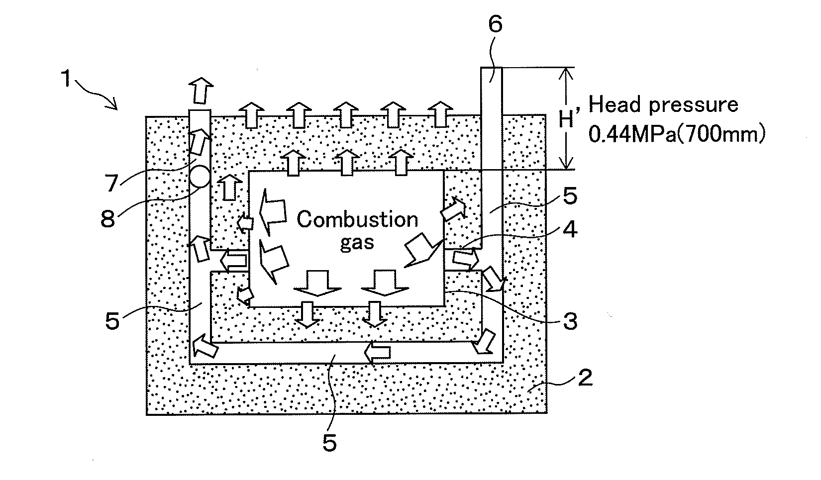
[0048]FIG. 1 shows a cross section of a mold 1 that schematically shows an evaporative pattern casting process relating to the First Embodiment of the present invention. The mold 1 includes a pattern 3 that is buried in casting sand 2 filled in a mold flask, which is not shown in FIG. 1.

[0049]A gate 4 connected to the pattern, and a runner 5 connected to the gate 4, are formed around the pattern 3 in the casting sand 2. The runner 5 is provided with plural openings (two openings in FIG. 1) to an upper surface of the mold 1, and one of the openings (on the right side in FIG. 1) is provided with a sprue 6. The runner 5 on the other opening side is specifically used as a gas discharge passage 7, and the gas discharge passage 7 is arranged with a filter 8 for discharging only combustion gas to the atmosphere outside of the mold 1.

[0050]The mold 1 is produced as follows. First, the surface of the pattern 3 is coated with a mold wash and is sufficiently dried. The mold ...

second embodiment

2. Second Embodiment

[0083]FIG. 6 shows a cross section of a mold 21 that schematically shows an evaporative pattern casting process relating to the Second Embodiment of the present invention. The mold 21 includes a pattern 23 that is buried in casting sand 22 filled in a mold flask, which is not shown in FIG. 6.

[0084]A gate 24 connected to the pattern, and a runner 25 connected to the gate 24, are formed around the pattern 23 in the casting sand 22. The runner 25 is provided with plural openings (two openings in FIG. 6) to an upper surface of the mold 21, and one of the openings (on the right side in FIG. 6) is provided with a sprue 26. The runner 25 on the other opening side is specifically used as a gas discharge passage 27, and the gas discharge passage 27 is arranged with a filter 28 for discharging only combustion gas to the atmosphere outside of the mold 21.

[0085]The mold 21 is produced as follows. First, the surface of the pattern 23 is coated with a mold wash and is sufficie...

third embodiment

3. Third Embodiment

[0112]FIG. 12 shows a cross section of a mold 31 that schematically shows an evaporative pattern casting process relating to the Third Embodiment of the present invention. The mold 31 includes a pattern 33 that is buried in casting sand 32 filled in a mold flask, which is not shown in FIG. 12.

[0113]A gate 34 connected to the pattern, and a runner 35 connected to the gate 34, are formed around the pattern 33 in the casting sand 32. The runner 35 is provided with plural openings (two openings in FIG. 12) to an upper surface of the mold 31, and one of the openings (on the right side in FIG. 12) is provided with a sprue 36. The runner 35 on the other opening side is specifically used as a gas discharge passage 37, and the gas discharge passage 37 is arranged with a filter 38 for discharging only combustion gas to the atmosphere outside of the mold 31.

[0114]The mold 31 is produced as follows. First, the surface of the pattern 33 is coated with a mold wash and is suffic...


PUM

PropertyMeasurementUnit
modulusaaaaaaaaaa
surface areaaaaaaaaaaa
casting timeaaaaaaaaaa

Abstract

An evaporative pattern casting process includes forming a mold by burying a pattern made of resin foam in casting sand, pouring molten metal into the mold, and evaporating the pattern with the molten metal and thereby casting a product. In the evaporative pattern casting process, casting time during founding is set according to a modulus (pattern volume÷pattern surface area) of the pattern. Accordingly, the casting time in the evaporative pattern casting process is accurately set with high precision.

Description

FIELD OF THE INVENTION[0001]The present invention relates to an evaporative pattern casting process.DESCRIPTION OF RELATED ART[0002]The following evaporative pattern casting process is generally known. In this process, a mold is formed in such a way that a pattern consisting of resin foam with a predetermined shape is buried in casting sand. Then, molten metal is poured into the mold, whereby the pattern is combusted and evaporated and is replaced with a casting. In regard to this process, a method of calculating appropriate casting time is disclosed in Japanese Unexamined Patent Application Laid-open No. 2003-340547. In this method, the casting time is calculated based on a ratio of casting time when molten metal is poured into a hollow space to casting time during the evaporative pattern casting process.[0003]In the evaporative pattern casting process, the temperature of the molten metal poured into the mold is decreased. Therefore, there may be cases in which residue defects resu...

Claims


Application Information

Patent Timeline
Patent Type & Authority Applications(United States)
IPC IPC(8): B22C9/04
CPCB22C9/046B22C7/023
Inventor HIRAI, FUMIOITO, OSAMIYAMADA, HIROYUKIICHIKAWA, HIROSHIHOKAZONO, HIDETAKAYAMAMOTO, TOMOHIKOMURAI, KOSUKE
Owner HONDA MOTOR CO LTD
Why Eureka
Try Eureka