Thermal dissipation substrate

Inactive Publication Date: 2012-11-01
NAT CHIAO TUNG UNIV
View PDF9 Cites 10 Cited by
  • Summary
  • Abstract
  • Description
  • Claims
  • Application Information

AI Technical Summary

Benefits of technology

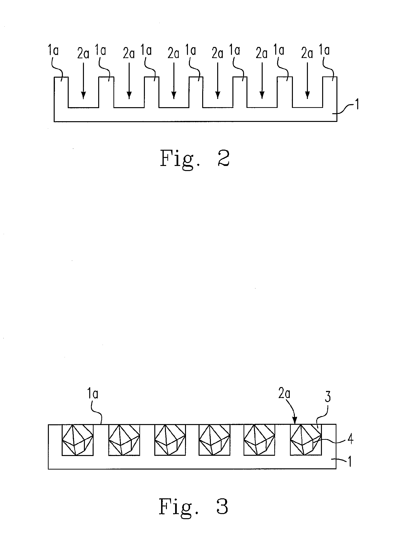
[0008]The present invention fills the patterned substrate with diamond pellets to fabrica

Problems solved by technology

Therefore, the thermal dissipation issue is getting more and more important, particularly on the high power or high frequency elements.
Taking a central processing unit (CPU) as an example, if the CPU overheats over a long period of time, it would cause the lifetime of the CPU be reduced, and the operating performanc

Method used


Image

  • Thermal dissipation substrate
  • Thermal dissipation substrate
  • Thermal dissipation substrate

Examples


embodiments

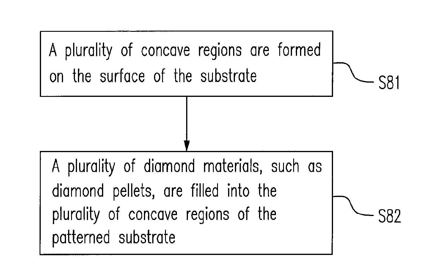
[0049]1. A method for manufacturing a thermal dissipation substrate, comprising steps of (a) providing a substrate body having a surface; (b) forming a plurality of concave regions on the surface; and (c) filling the plurality of concave regions with a plurality of diamond materials.

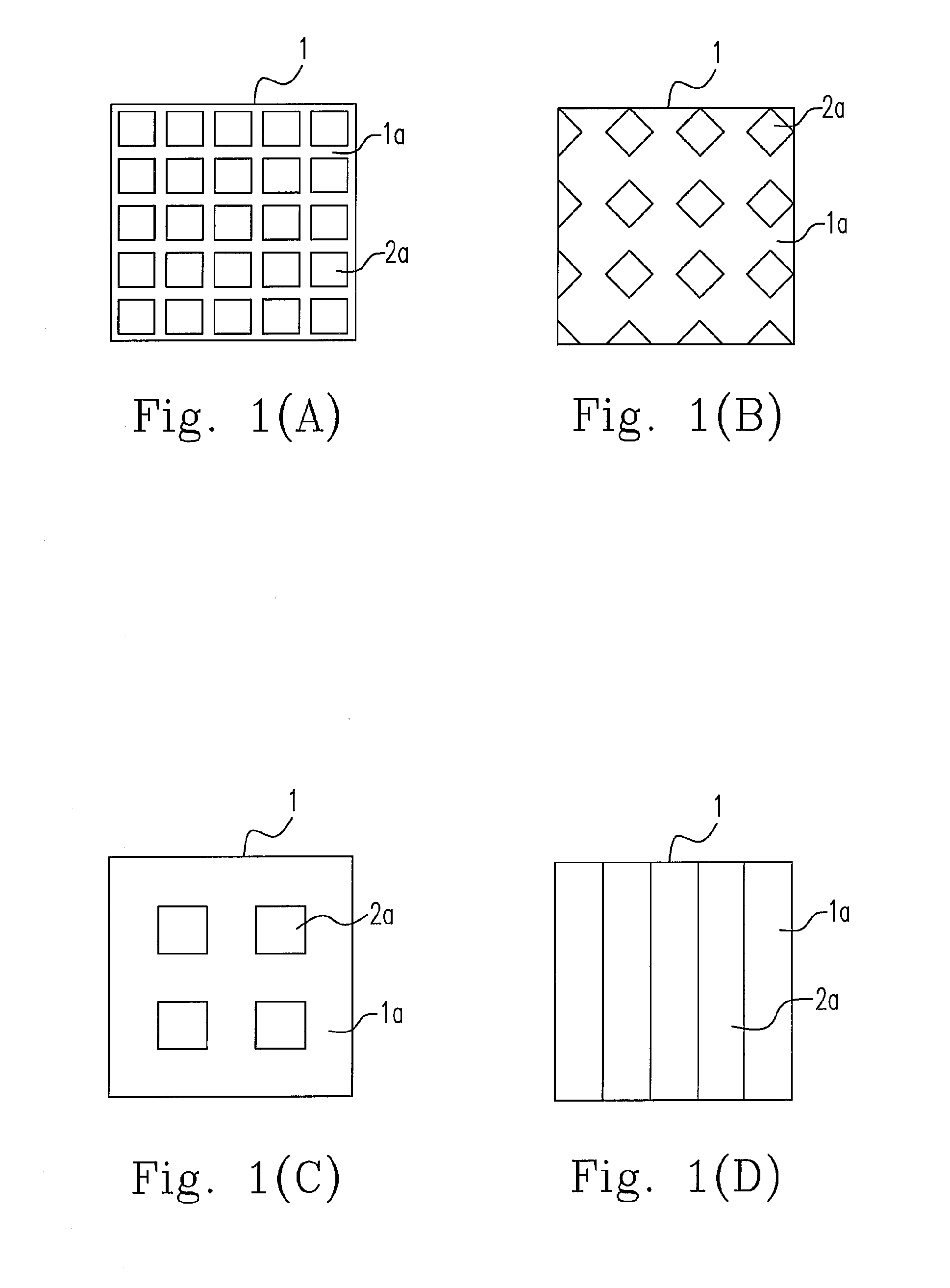
[0050]2. The method according to the previous embodiment, wherein the step (b) further comprises a step of using an etching method for patterning the surface to form the plurality of concave regions for correspondingly presenting a plurality of protruding regions.

[0051]3. The method according to any one of the previous embodiments, wherein the etching method is one of a chemistry wet etching and a dry etching.

[0052]4. The method according to any one of the previous embodiments further comprising a step (d) of bonding the substrate body and an electronic element by a wafer bonding technique.

[0053]5. The method according to any one of the previous embodiments further comprising a step (e) of cutting the bo...


PUM


Abstract

The present invention related to a method for manufacturing a thermal dissipation substrate and a thermal dissipation substrate. The method includes steps of: (a) providing a substrate body having a surface; (b) forming a plurality of concave regions on the surface; and (c) filling the plurality of concave regions with a plurality of diamond materials. The thermal dissipation substrate includes: a substrate having a surface at a first horizontal; a plurality of regions formed on the surface at a second horizontal; and a plurality of diamond materials having a relatively high thermal coefficient and disposed on the plurality of regions.

Description

FIELD OF THE INVENTION[0001]The present invention relates to a thermal dissipation substrate, and more particularly to a thermal dissipation substrate for high power semiconductors or electronic elements.BACKGROUND OF THE INVENTION[0002]With the development of the processing technique and the requirement of the electronic products, it is a trend to continuously get high efficiency and small size for semiconductors. Therefore, the thermal dissipation issue is getting more and more important, particularly on the high power or high frequency elements.[0003]Taking light emitted diodes (LED) as an example, although the LED products are applied popularly due to many advantages, such as energy saving, power saving, high efficiency and etc., the efficiency of light emitting for the LEDs is influenced by the temperature. Therefore, if the thermal energy generated by the LEDs can not be conducted out, the temperature of the LEDs would be thus raised, which influences the efficiency of light e...

Claims


Application Information

Patent Timeline
IPC IPC(8): H01L29/02H01L21/50
CPCH01L23/142H01L23/147H01L23/3732H01L21/4871H01L2924/0002H01L33/641H01L2924/00
Inventor WU, YEWCHUNG SERMONCHANG, TAI-MINCHIU, YU CHIAHU, JEN-LI
Owner NAT CHIAO TUNG UNIV
Why Eureka
Try Eureka