Light emitting device and illumination apparatus including same

a technology of light emitting devices and illumination apparatus, which is applied in the direction of discharge tubes/lamp details, lighting and heating apparatus, discharge tubes luminescnet screens, etc., can solve the problems of surface reflection, difficult control of light distribution, and granule-like distribution of lights, so as to achieve easy control of light distribution and widen the effect of light distribution

Inactive Publication Date: 2012-11-01
PANASONIC CORP
View PDF5 Cites 13 Cited by
  • Summary
  • Abstract
  • Description
  • Claims
  • Application Information

AI Technical Summary

Benefits of technology

[0006]In view of the above, the present invention provides a light emitting device which is capable of widening a light distribution of output lights, providing easy controllability of the light distribution, and preventing non-uniform light distribution, and an illumination apparatus including the light emitting device.
[0015]In accordance with the aspects of the present invention, since more lights propagate in the lateral direction of the solid-state light emitting element than in the vertical direction thereof in the cross section of the wavelength converting member, the lights emitted from the wavelength converting member have a so-called pad wing type light distribution curve thereby to widen a light distribution. Further, since more lights propagate in the lateral direction, it is easy to control the light distribution by using a reflector in addition, when the illumination emitting device is incorporated in a lighting apparatus, the light emitting device provides a low directivity, thereby preventing the occurrence of non-uniform light distribution.

Problems solved by technology

Therefore, even if a reflector is provided to cover the LED package, it is difficult to control the distribution of lights since the amount of lights incident into the reflector is low.
This results in a non-uniform distribution of luminance at the output surface (the diffusion and transmission panel 107) of the illumination apparatus, thereby resulting in a granule-like distribution of the lights, and causing surface reflection.

Method used


Image

  • Light emitting device and illumination apparatus including same
  • Light emitting device and illumination apparatus including same
  • Light emitting device and illumination apparatus including same

Examples


first embodiment

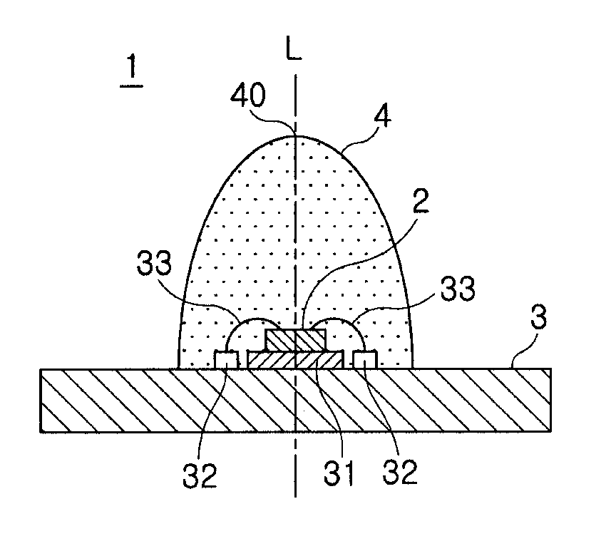
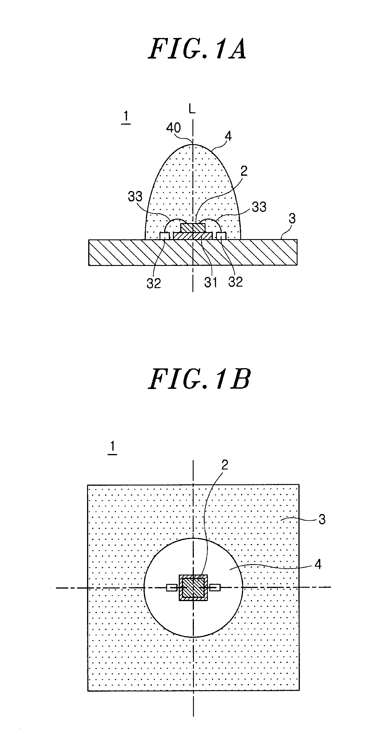
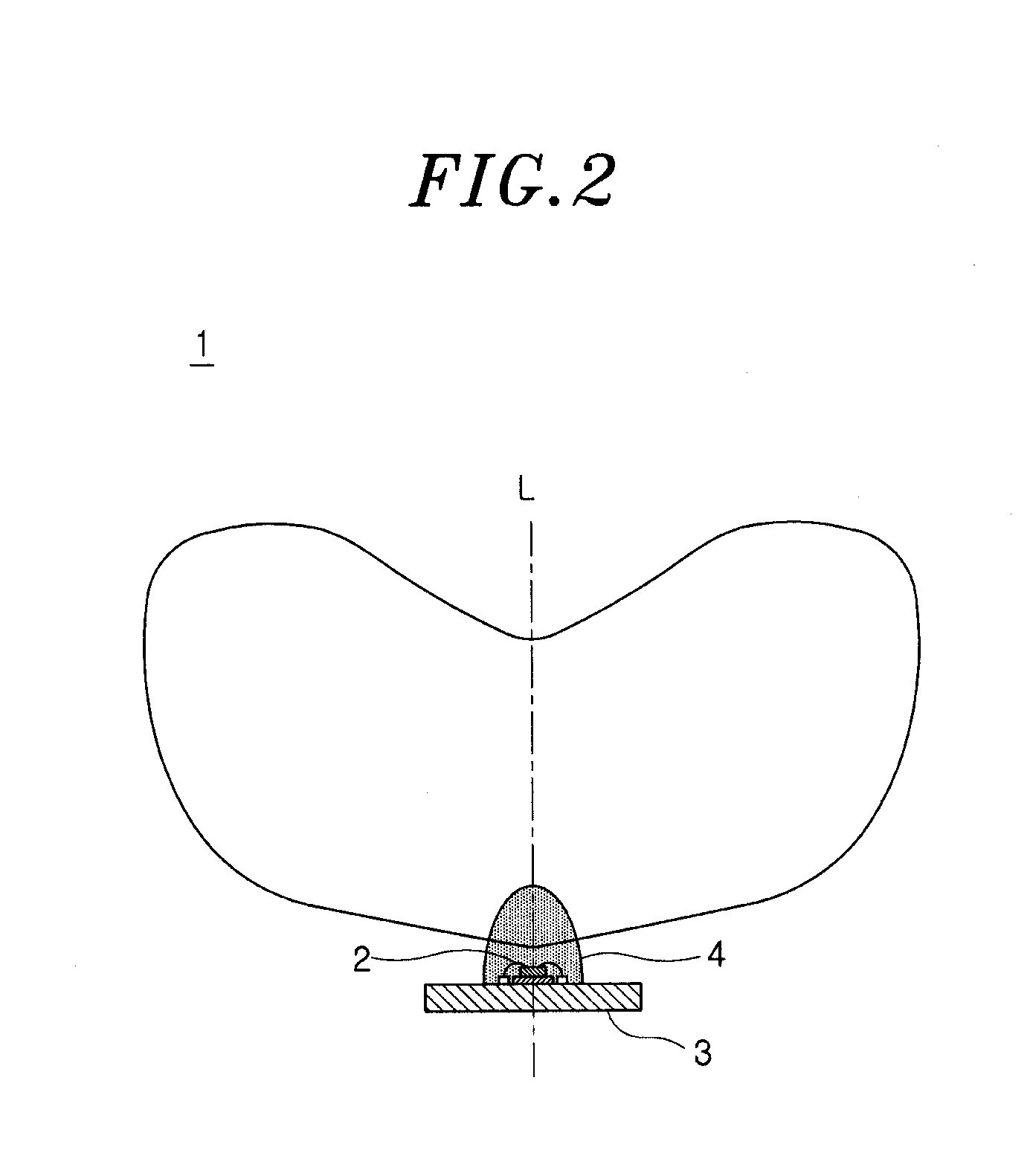
[0028]Hereinafter, a light emitting device and an illumination apparatus including same in accordance with the present invention will be described with reference to FIGS. 1A to 4B. In this embodiment, as shown in FIG. 1A, a light emitting device 1 includes a light emitting diode (LED) 2 as a solid-state light emitting element; a wiring board (hereinafter abbreviated as a “board”) 3 on which the LED 2 is mounted; and a wavelength converting member 4 made of a transparent resin member containing a fluorescent material, the resin member coating an output surface of the LED 2.

[0029]The wavelength converting member 4 is formed to have a thickness larger in a vertical direction of the LED 2 than that in a lateral direction of the LED 2 in a vertical cross section that is parallel to a light output direction of the LED 2 (hereinafter, simply referred to as “vertical cross section”), and includes a zenith 40 in the light output direction of the LED 2. In the following description, a normal ...

fourth embodiment

[0072]Next, a light emitting device in accordance with the present invention will be described. with reference to FIG. 9. In this embodiment, a light emitting device 1 includes a wavelength converting member 4 having a concave portion 41 formed. in the side facing an LED 2. The wavelength converting member 4 is formed as a thin member 42 having uniform. thickness, the concave portion 41 being filled with a transparent resin 43. The thin member 42 is a member formed by coating the transparent resin 43 with a resin containing a fluorescent material to cover the LED 2, or a resin member containing a fluorescent material molded into a cap shape. Thickness of the wavelength converting member 4 (thin member 42) ranges from 0.1 to 0.5 mm, for example. The transparent resin 43 is the same resin as the thin member 42 except that it contains no fluorescent material. For example, the transparent resin 43 may be a silicone resin. Ether configurations are the same as those of the above-described...


PUM


Abstract

A light emitting device includes a solid-state light emitting element; and a wavelength converting member made of a transparent resin containing a fluorescent material, the transparent resin being coated on an output surface of the solid-state light emitting element. The wavelength converting member is formed to have a thickness larger in a vertical direction of the solid-state light emitting element than that in a lateral direction of the solid-state light emitting element in a cross section that is parallel to a light output direction of the solid-state light emitting element and have a zenith in the light output direction.

Description

FIELD OF THE INVENTION[0001]The present invention relates to a light, emitting device including a plurality of solid-state light emitting elements as a light source, and an illumination apparatus including the light emitting device.BACKGROUND OF THE INVENTION[0002]Because of their low power consumption, high luminance and high durability, light emitting diodes (LEDs) are in the spotlight as a light source for an illumination apparatus with which incandescent lamps, fluorescent lamps and the like are replaced. However, since a single LED provides less light intensity than a fluorescent lamp, a light emitting device including a plurality of LEDs is used for a general illumination apparatus having LEDs as a light source.[0003]As one example of LED packages for such a type of light emitting device, there has been known an LED package in which a yellow fluorescent-material layer is coated on an LED chip emitting a blue light, wherein the blue light and a yellow light are mixed to thereby...

Claims


Application Information

Patent Timeline
Patent Type & Authority Applications(United States)
IPC IPC(8): H01J1/70
CPCH01L33/505H01L2224/48091H01L2224/45147H01L33/54H01L2224/45144H01L2924/00014H01L2924/00H01L24/45H01L2224/45124H01L2224/45139H01L2924/12041H01L2924/181H01L33/508H01L2924/00012
Inventor YOKOTANI, RYOJI
Owner PANASONIC CORP
Why Eureka
Try Eureka