High-frequency signal transmission line

a high-frequency signal and transmission line technology, applied in the direction of waveguides, waveguide type devices, high-frequency circuit adaptations, etc., can solve the problems of increased capacitance between the signal line and the grounding conductor, increased thickness of the high-frequency signal transmission line, and unnecessary radiation from the signal line b>502/b>, so as to reduce unnecessary radiation and reduce loss

Active Publication Date: 2012-11-01
MURATA MFG CO LTD
View PDF1 Cites 48 Cited by
  • Summary
  • Abstract
  • Description
  • Claims
  • Application Information

AI Technical Summary

Benefits of technology

[0018]A high-frequency signal transmission line according to a preferred embodiment of the present invention is thin but has reduced unnecessary ra

Problems solved by technology

However, the increase in the areas of the grounding conductors opposed to the signal line caused by the increase in width of the signal line leads to an increase in capacitances among the signal line and the grounding conductors.
However, the increase in distances among the signal line and the grounding conductors leads to an increase in thickness of the high-frequency signal transmission line, which is an obstacle to achievement of a flexible high-frequency signal transmission line.
However, the high-frequency signal transmission line 500 has a problem in that unnecessary radiation from the signal line 502 occurs.
Moreov

Method used


Image

  • High-frequency signal transmission line
  • High-frequency signal transmission line
  • High-frequency signal transmission line

Examples


first preferred embodiment

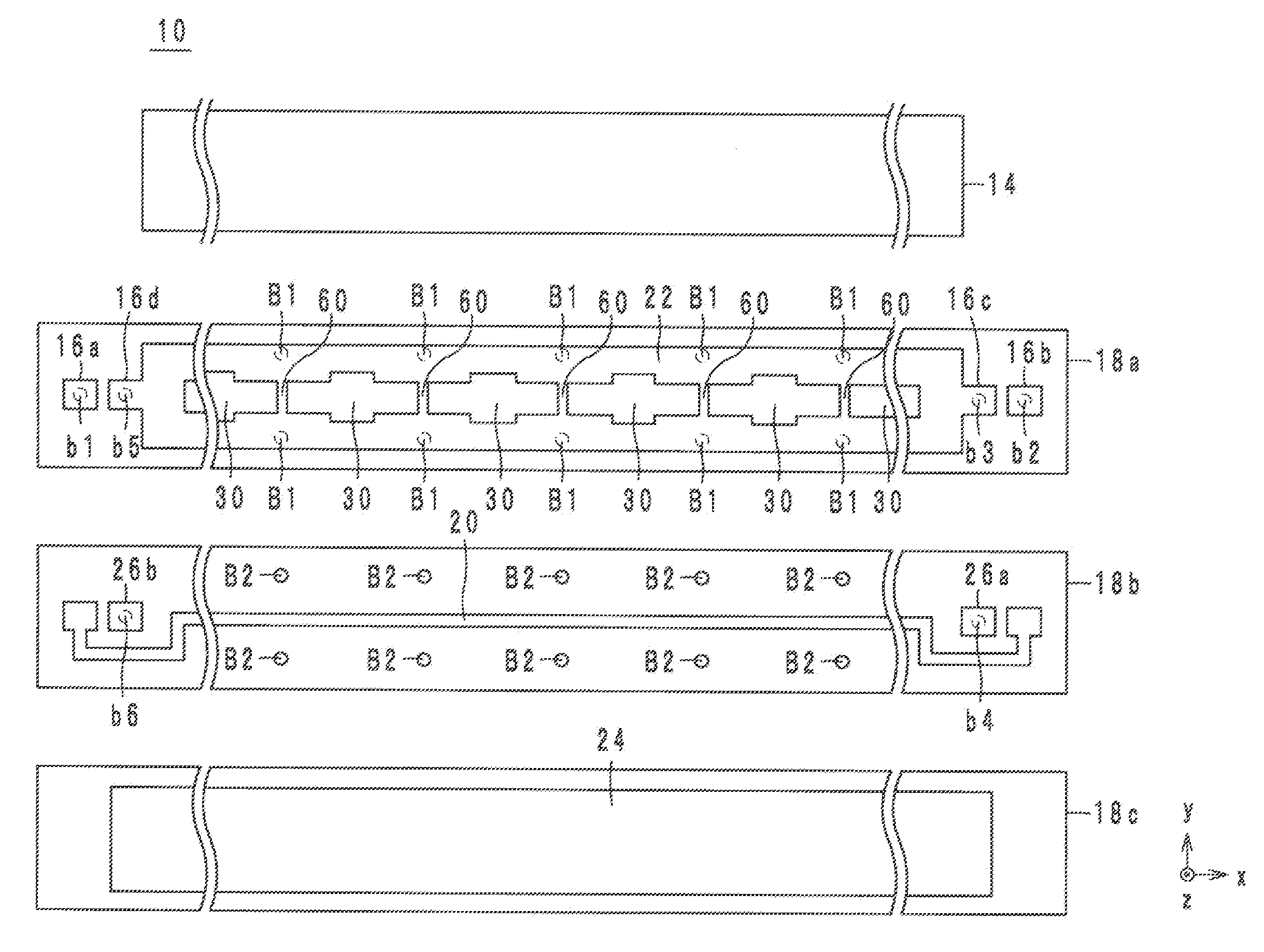
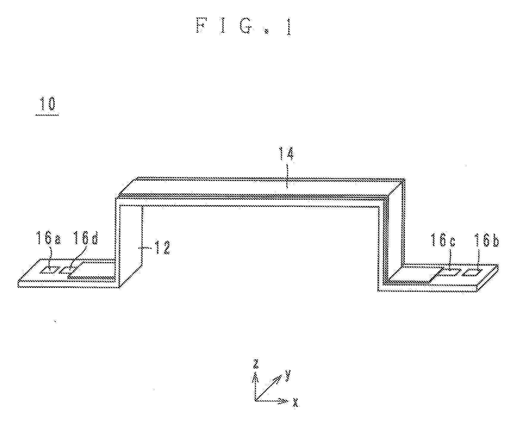
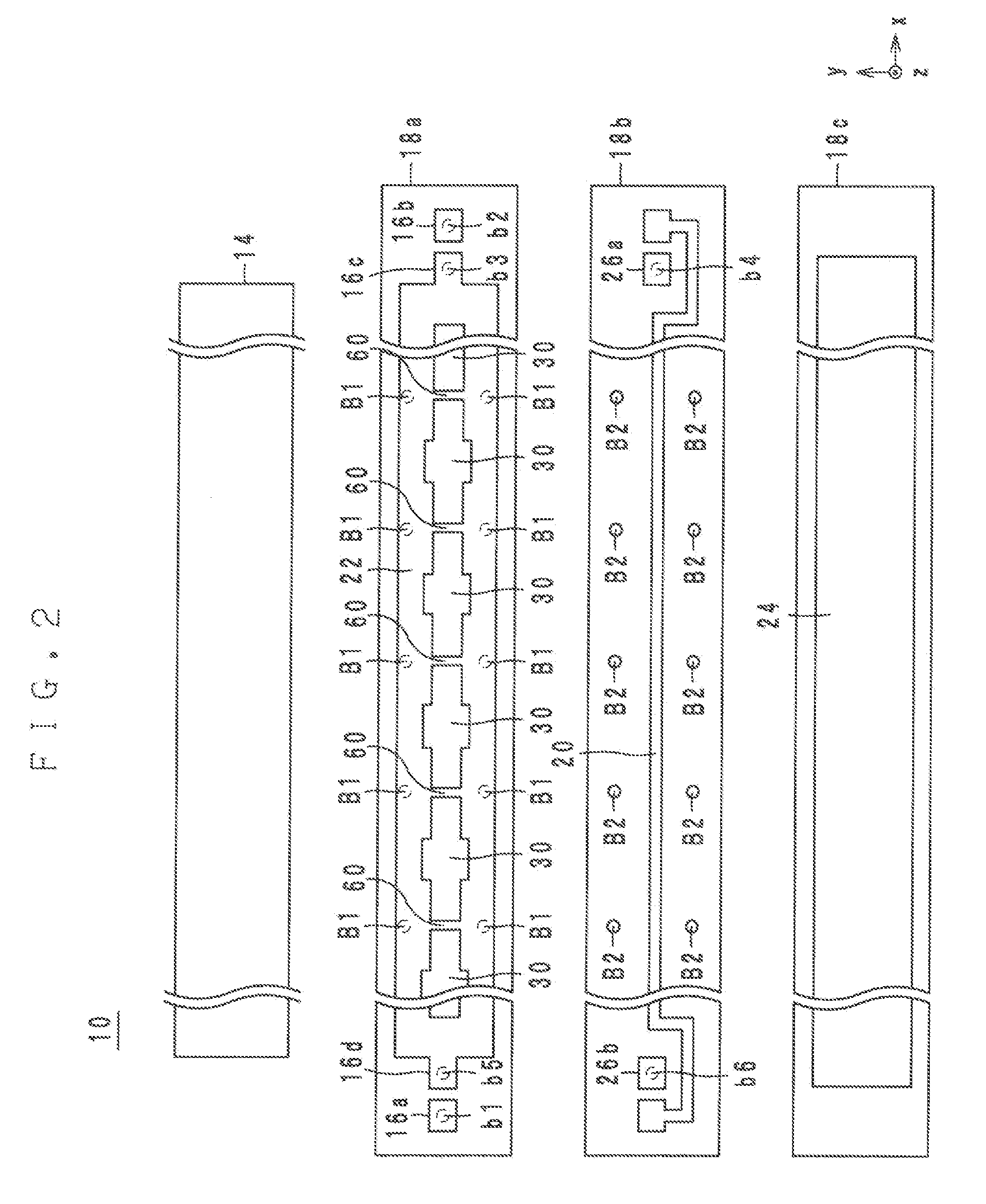
[0038]The structure of a high-frequency signal transmission line according to a first preferred embodiment is hereinafter described with reference to the drawings. FIG. 1 is a perspective outline view of the high-frequency signal transmission line 10 according to the first preferred embodiment of the present invention. FIG. 2 is an exploded view of the high-frequency signal transmission line 10. FIG. 3 is a transparent view of the high-frequency signal transmission line 10, viewed from the top of a lamination direction. FIG. 4 is a cross-sectional view of the high-frequency signal transmission line 10. FIG. 5 is an equivalent circuit diagram of a portion of the high-frequency signal transmission line 10. In FIGS. 1 to 4, the lamination direction of the high-frequency signal transmission line 10 is defined as a z-axis. The longitudinal direction of the high-frequency signal transmission line 10 is defined as an x-axis, and the direction perpendicular to the x-axis and the z-axis is d...

second preferred embodiment

[0091]In the following, a high-frequency signal transmission line according to a second preferred embodiment will be described with reference to the drawings. FIG. 6 is an exploded view of the high-frequency signal transmission line 10a according to the second preferred embodiment. FIG. 7 is a graph showing the impedance of the signal line 20 of the high-frequency signal transmission line 10a according to the second preferred embodiment.

[0092]The high-frequency signal transmission line 10a is different from the high-frequency signal transmission line 10 in that openings 30a provided in the grounding conductor 22 in the high-frequency signal transmission line 10a are of a different shape from the openings 30. While the y-axis dimension of each of the openings 30 changes step by step as shown by FIG. 2, the y-axis dimension of each of the openings 30a changes continuously. More specifically, each of the openings 30a has a smaller y-axis dimension the farther its location from the x-ax...

third preferred embodiment

[0096]In the following, a high-frequency signal transmission line according to a third preferred embodiment will be described with reference to the drawings. FIG. 8 is an exploded view of the high-frequency signal transmission line 10b according to the third preferred embodiment.

[0097]The high-frequency signal transmission line 10b is different from the high-frequency signal transmission line 10 in that the high-frequency signal transmission line 10b preferably also includes grounding conductors 40 and 42. Specifically, in the high-frequency signal transmission line 10b, on the front surface of the dielectric sheet 18b, that is, on the same surface on which the signal line 20 is provided, the grounding conductors 40 and 42 are provided. The grounding conductor 40 is a rectangular conductor that is located in the positive side of the signal line 20 in the y-axis and that extends along the x-axis. The grounding conductor 40 is connected to the grounding conductors 22 and 24 via the vi...


PUM


Abstract

A flexible high-frequency signal transmission line includes a dielectric body including laminated flexible dielectric layers. A signal line is provided in the dielectric body. A grounding conductor is arranged in the dielectric body to be opposed to the signal line via one of the dielectric layers. The grounding conductor is of a ladder structure including a plurality of openings and a plurality of bridges arranged alternately along the signal line. A characteristic impedance of the signal line changes between two adjacent ones of the plurality of bridges such that the characteristic impedance of the signal line rises from a minimum value to an intermediate value and to a maximum value and falls from the maximum value to the intermediate value and to the minimum value in this order.

Description

BACKGROUND OF THE INVENTION[0001]1. Field of the Invention[0002]The present invention relates to a high-frequency signal transmission line, and more particularly to a thin flexible high-frequency signal transmission line.[0003]2. Description of the Related Art[0004]In a high-frequency signal transmission line of a tri-plate stripline structure wherein a signal line is sandwiched between an upper and a lower grounding conductor, one way of decreasing the resistance to high-frequency waves is to increase the width of the signal line. Specifically, by increasing the width of the signal line, the surface area of the signal line is increased, and accordingly, the areas of the grounding conductors opposed to the signal line are increased. Therefore, the resistance of the signal line to high-frequency waves can be reduced.[0005]However, the increase in the areas of the grounding conductors opposed to the signal line caused by the increase in width of the signal line leads to an increase in...

Claims


Application Information

Patent Timeline
IPC IPC(8): H01P3/08
CPCH01P1/20363H01P3/08H05K1/0221H05K1/0225H05K1/0242H01P3/085H05K1/028H05K2201/09618H05K2201/0969H05K2201/09727H05K1/0253H01P5/08H01P3/003H03H7/38
Inventor KATO, NOBORU
Owner MURATA MFG CO LTD
Why Eureka
Try Eureka