Metamaterial reconfigurable antennas

a technology of metal materials and antennas, applied in the direction of antenna details, non-resonant long antennas, antennas, etc., can solve the problems of low gain or impedance mismatch in antenna configurations, and achieve high pattern and polarization reconfigurability and good impedance matching

Inactive Publication Date: 2012-11-01
ADANT TECH
View PDF0 Cites 23 Cited by
  • Summary
  • Abstract
  • Description
  • Claims
  • Application Information

AI Technical Summary

Benefits of technology

[0005]To address the above-mentioned needs in the art, the invention described herein uses leaky wave antennas (LWAs) built using metamaterial structures loaded with tunable capacitors and inductors and specific DC bias networks to control the values of capacitance and inductance across the antenna. Three different reconfigurable antenna designs built using a LWA metamaterial structure are described. These antennas exploit the characteristics of Composite Right Left Handed (CRLH) materials to achieve high pattern and polarization reconfigurability, with good impedance matching in a compact antenna design.
[0006]In particular, the invention includes metamaterial reconfigurable antennas that uses varactor diodes to change characteristics of unit cell structures such as group delay of transmission lines, polarization and impedance, by changing the values of variable capacitors and / or inductors in response to independent DC biases provided by independent DC bias circuits. As they operate on a traveling wave and not a resonating wave basis, these antennas may enable significant improvements in gain and reconfigurability. By controlling the varactor diodes independently, the group delay, polarization and impedance may be more widely varied than standard unit cell structures that only change the group delay.

Problems solved by technology

Using these techniques allows generating different polarizations and radiation patterns but, especially when the antenna has several different configurations, it generally causes some of the antenna configurations to suffer of low gain or impedance mismatch.

Method used


Image

  • Metamaterial reconfigurable antennas
  • Metamaterial reconfigurable antennas
  • Metamaterial reconfigurable antennas

Examples


Embodiment Construction

[0038]A detailed description of illustrative embodiments of the present invention will be described below with reference to FIGS. 1-23. Although this description provides detailed examples of possible implementations of the present invention, it should be noted that these details are intended to be exemplary and in no way delimit the scope of the invention.

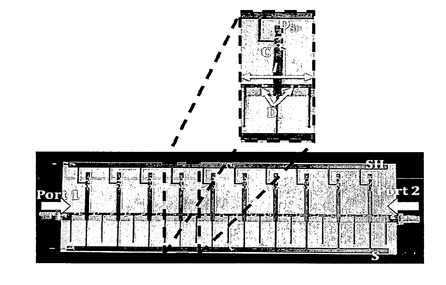
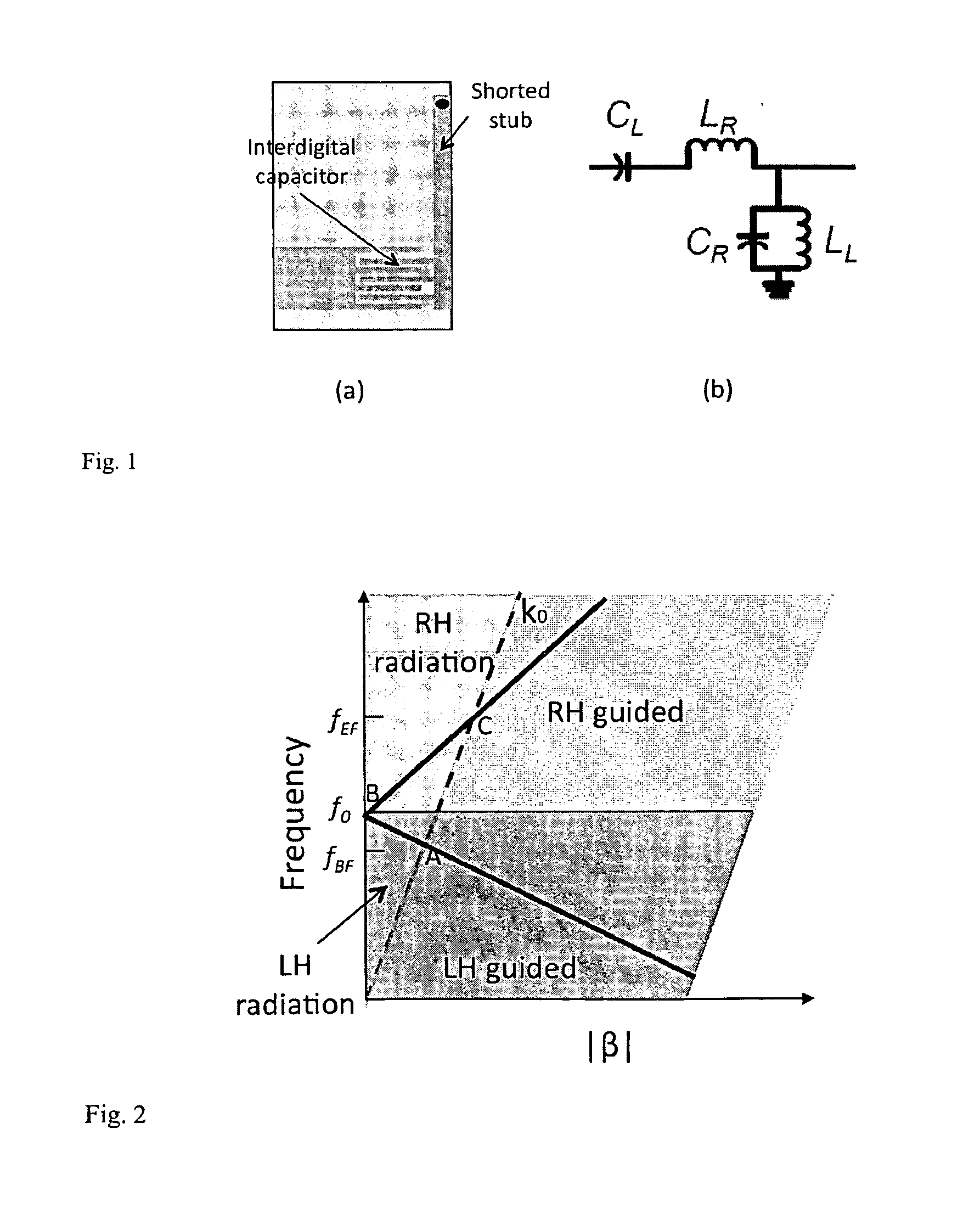
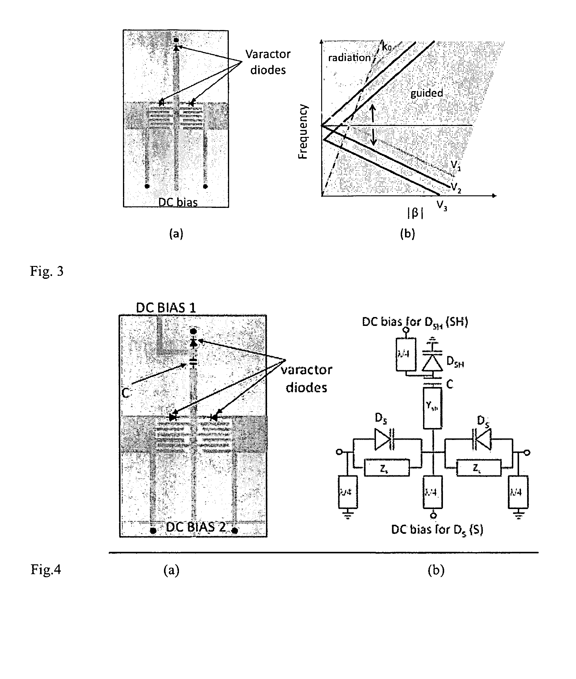
[0039]A leaky wave is a traveling wave that progressively leaks out power while it propagates along a waveguiding structure. Such structures are usually used as antennas to achieve high directivity. Leaky wave antennas are fundamentally different from resonating antennas in the sense that they are based on a traveling wave as opposed to a resonating wave mechanism. Significantly, the antenna size is not related to the antenna resonant frequency but to its directivity.

[0040]The radiation properties of a leaky wave antenna are related to the propagation constant along the direction of the waveguide, γ=α−jβ (where α is the attenuatio...


PUM


Abstract

Leaky wave antennas that can be reconfigured in pattern and / or polarization by exploiting the characteristic of metamaterial structures loaded with variable capacitor and inductors employ a Composite Right Left Handed (CRLH) unit cell with two independent DC biases used to actively change the group delay of the transmission line and the polarization of the radiated field while preserving good impedance matching. Different degrees of pattern and polarization reconfigurability are achieved by cascading multiple of these unit cells along a straight line, a circular line or a zigzag line while preserving high gain for all the antenna configurations and good impedance matching.

Description

CROSS REFERENCE TO RELATED APPLICATIONS[0001]This application claims benefit of U.S. Provisional Application No. 61 / 286,786 filed Dec. 16, 2009.TECHNICAL FIELD[0002]The present invention relates generally to the field of reconfigurable antennas. Specifically, the present invention relates to antennas that can be reconfigured in pattern and / or polarization by using metamaterial structures loaded with variable capacitor and inductorsBACKGROUND OF THE INVENTION[0003]The changing behavior of the wireless channel causes fluctuations in the level of received signal power. In order to limit the effect of the varying wireless channel on system performance, a possible solution is to adopt reconfigurable antenna systems capable of adaptively tuning their radiation characteristics in response to the multivariate channel. Radiation pattern shape, polarization state and frequency of operation can be tuned to accommodate the operating requirements. Different solutions employing different techniqu...

Claims


Application Information

Patent Timeline
Patent Type & Authority Applications(United States)
IPC IPC(8): H01Q21/22
CPCH01Q3/00H01Q13/28H01Q15/0006H01Q11/02H01Q1/2216H01Q3/01H01Q23/00
Inventor PIAZZA, DANIELED'AMICO, MICHELE
Owner ADANT TECH
Why Eureka
Try Eureka