Method and particle analyzer for determining a broad particle size distribution

a particle size and distribution technology, applied in the field of methods and particle analyzers, can solve the problems of high inconvenient use of different particle analyzers to determine the sizes of particles of an upper size range and particles of a lower size range in the same liquid sample, and the differences in the size of particles determined by the different particle analyzers

Active Publication Date: 2012-11-01
PROTEINSIMPLE
View PDF7 Cites 28 Cited by
  • Summary
  • Abstract
  • Description
  • Claims
  • Application Information

AI Technical Summary

Problems solved by technology

However, as NTA requires the capture of several dark-field image frames, the rate of analysis is relatively low.
Although both bright-field and dark-field imaging particle analyzers are separately known, the use of different particle analyzers to determine the sizes of particles of an upper size range and particles of a lower size range in the same liquid sample is highly inconvenient.
Furthermore, the sizes determined by the different particle analyzers oft

Method used


Image

  • Method and particle analyzer for determining a broad particle size distribution
  • Method and particle analyzer for determining a broad particle size distribution
  • Method and particle analyzer for determining a broad particle size distribution

Examples


first embodiment

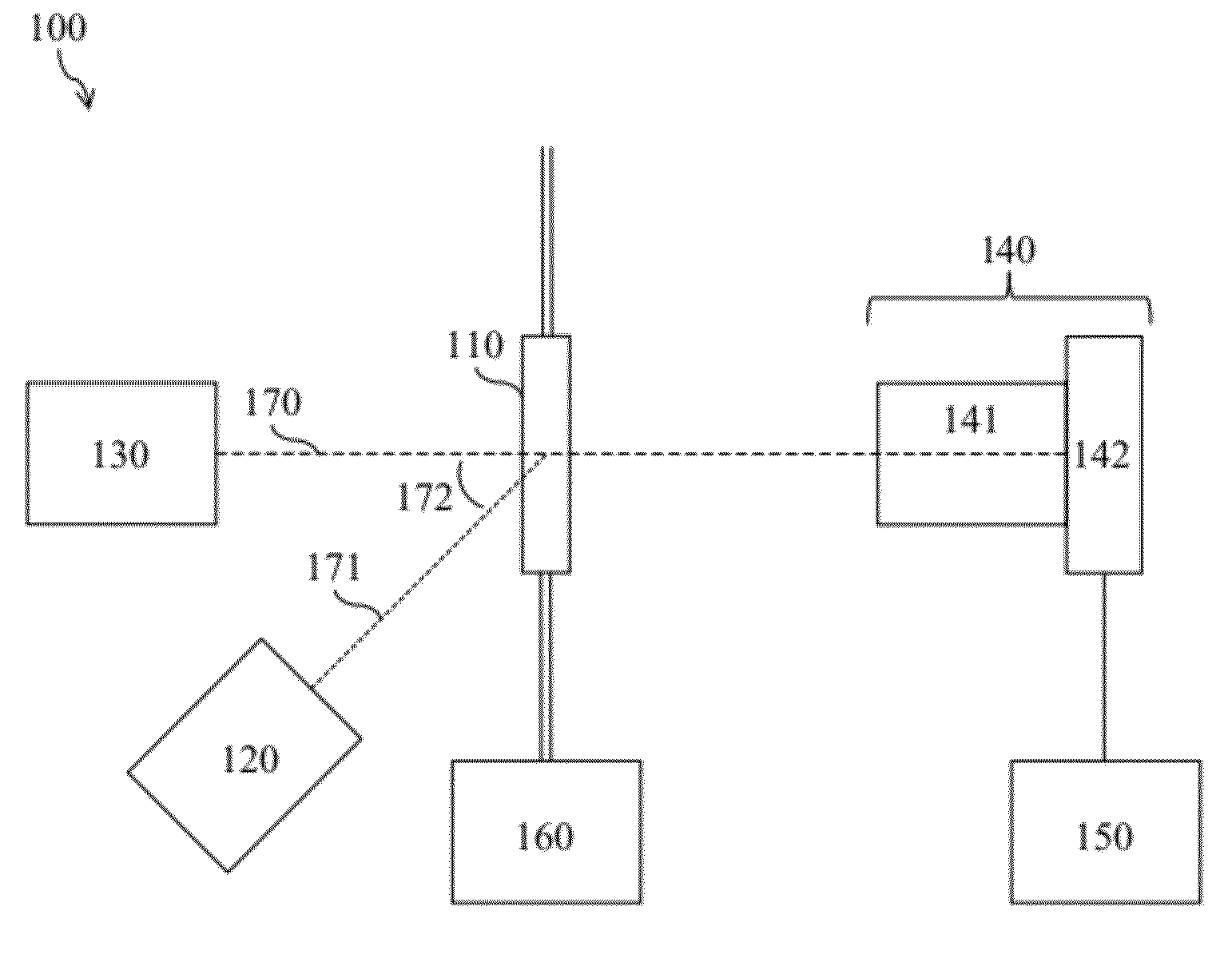
[0021]With reference to FIG. 1, the particle analyzer 100 includes a sample cell 110, a dark-field light source 120, a bright-field light source 130, an imaging system 140, a processing system 150, and a pumping system 160. The imaging system 140 typically includes a magnification system 141 and a detector array 142. The processing system 150 typically includes a control module and an analysis module (not shown). The bright-field light source 130, the sample cell 110, the magnification system 141, and the detector array 142 are aligned along an optical axis 170. The dark-field light source 120 and the sample cell 110 are aligned along a direction 171 at an angle 172 to the optical axis 170.

[0022]Typically, the sample cell 110, which holds the liquid sample, is a flow cell. The pumping system 160 passes the liquid sample in a flowing stream into the sample cell 110. Preferably, the pumping system 160 is a pulse pumping system, as described in U.S. Pat. No. 7,307,721, which passes the...

third embodiment

[0054]With reference to FIG. 5, the particle analyzer 500 is useful in instances where some of the particles in the liquid sample are fluorescent particles, having either natural fluorophores or fluorophore tags, which emit fluorescent light in a first wavelength band after absorbing light in a second wavelength band.

[0055]The third embodiment of the particle analyzer 500 is similar to the first embodiment, but includes an additional fluorescence light source 580 that is aligned with the sample cell 110 along a direction 573 at an angle 574 to the optical axis 170, and an imaging system 540 comprising a wavelength selective filter 543. The angle 574 may be any angle.

[0056]The fluorescence light source 580 illuminates the liquid sample in the sample cell 110 with light in the second wavelength band to yield fluorescent light in the first wavelength band, as well as scattered light in the second wavelength band. The dark-field light source 120 and the bright-field light source 130 ill...


PUM


Abstract

A method and a particle analyzer are provided for determining a particle size distribution of a liquid sample including particles of a lower size range, particles of an intermediate size range, and particles of an upper size range. A dark-field image frame is captured in which the particles of the lower size range and the particles of the intermediate size range are resolved, and a bright-field image frame is captured in which the particles of the intermediate size range and the particles of the upper size range are resolved. Absolute sizes of the particles of the intermediate size range and the particles of the upper size range are determined from the bright-field image frame. Calibrated sizes of the particles of the lower size range are determined from the dark-field image frame by using the particles of the intermediate size range as internal calibration standards.

Description

TECHNICAL FIELD OF THE INVENTION[0001]The present invention relates to methods and particle analyzers for determining particle size distributions of liquid samples. More particularly, the present invention relates to methods and particle analyzers for determining particle size distributions by using bright-field and / or dark-field imaging.BACKGROUND OF THE INVENTION[0002]The determination of particle size distributions of liquid samples is necessary in pharmaceutical, life-science, and environmental-science applications, among others. The liquid samples may include dispersed particles of sizes ranging from less than 0.1 μm to 1000 μm. Generally, different types of particle analyzer are used to determine the sizes of particles of different size ranges.[0003]Bright-field imaging particle analyzers may be used to determine the sizes of particles larger than about 0.5 μm in a liquid sample. For example, micro-flow imaging (MFI) particle analyzers are described in U.S. Pat. No. 7,064,826 ...

Claims


Application Information

Patent Timeline
IPC IPC(8): H04N7/18
CPCG01N2015/1486G01N2015/1493G01N15/1463G01N21/64G01N15/0227G01N21/51G01N21/53G01N15/0211
Inventor KING, FREDERICK DAVIDMERCHANT, CLARK ADRIENOMA, PETER
Owner PROTEINSIMPLE
Why Eureka
Try Eureka